That's right. More precisely, mains gnd (I'll stick to calling it earth for clarity) is brought to the screw mount hole by R2, where it connects to the chassis. R3 appears (that's a guess as I cannot see the bottom of the pcb) to do the same for the signal gnd.
So yes, removing R3 should separate signal ground and earth.
So yes, removing R3 should separate signal ground and earth.
Mixi, have you tried different mains receptacles in your home? Sometimes a circuit in a home is particularly noisy, especially if it is shared with something like a refrigerator.
Also: in my previous house, I pulled off one of my receptacle covers and found that the earth lead wasn't actually connected to anything (or maybe it was tied to neutral, I'm not 100% sure now). But in either case, it definitely wasn't a separate pathway (as it should be), because when I pulled the receptacle housing out of the wall, there was exactly two wires coming off it.
Just a thought. Also, if you have a friend/relative nearby (in a different house), it might be worth a try to see if the hum exists there as well. Just trying to rule out your home's wiring as a potential source of the hum.
Matt,
I expect you still had a separate earth connection. Based on what I've heard and read, as well as observed on relative's homes in your area, Chicago is at variance with the rest of the USA in that it requires that all residential wiring be run inside metal conduit and that the electrical boxes in your walls be metal. Thus there is an electrical connection between your main electrical panel and any electrical box (such as the one that you opened up) via the conduit. On a receptacle, the metal strap band that screws the receptacle to the box is connected to the 'earth' sockets (third pin) and to the green ground/earth screw. There is also usually a spring metal clip thingie at one of the receptacle's mounting screws. Thus even with only two wires (likely white and black) screwed to the receptacle, as long as it is securely screwed to the metal box, you should have earth (safety ground) continuity. Personally, I'd prefer a separate earth wire, but per code it's covered by conduit.
Most of the rest of the USA allows Romex and plastic boxes in residential wiring, though conduit is required in commercial construction. Chicago appears interested in keeping electricians fully employed.
BrianL - file that under why didn't I think of that? Makes total sense: save a bit of the added cost of conduit by eliminating the third conductor and use the conduit itself! I don't live in that house any more, but it was constructed in 2013 IIRC, so that practice must be code compliant (though Chicago is also famous for bribery, so that's not necessarily a valid conclusion).
Sorry for the off-topic!
Sorry for the off-topic!
Tiny bit more progress this evening...
Light-bulb tester (with everything connected internally, but no signal or load attached), glowed medium bright for around a second and then faded quickly to nothing. As I understand it, that is what it is supposed to do.
Then, measured the DC voltage at the output of each channel. 4.0mV and 4.5mV so that also seems good.
Next test, apply some signal and a dummy load and see if it is amplified...
I heard music!
Did a couple more tests last night (testing levels into and out of the amplifier). Finally, I couldn't put it off any longer and I had to connect it up to source and speakers.
And...
No drama - it just worked!
Now I don't consider myself any kind of audiophile and I am also quite familiar with how we humans manage to kid ourselves into believing that we are hearing what we want to hear. So, I'm not going to try and describe what I heard, other than to say that it sounded good to my ears. I'll listen some more and if I feel confident enough to describe how it sounds, I'll report back.
Listened at moderate levels and the heatsink was barely above ambient temperature, so clearly the two amplifier chips onto the single chassis heatsink is fine.
Only positive things to say about these Neurochrome PCBs and documentation.
Thanks everyone here that helped me complete my first diyAudio project.")
Did a couple more tests last night (testing levels into and out of the amplifier). Finally, I couldn't put it off any longer and I had to connect it up to source and speakers.
And...
No drama - it just worked!
Now I don't consider myself any kind of audiophile and I am also quite familiar with how we humans manage to kid ourselves into believing that we are hearing what we want to hear. So, I'm not going to try and describe what I heard, other than to say that it sounded good to my ears. I'll listen some more and if I feel confident enough to describe how it sounds, I'll report back.
Listened at moderate levels and the heatsink was barely above ambient temperature, so clearly the two amplifier chips onto the single chassis heatsink is fine.
Only positive things to say about these Neurochrome PCBs and documentation.
Thanks everyone here that helped me complete my first diyAudio project.
That's so, so true!Ground is an ambiguous term, don't confuse it with earth (PE)
We have:
- AC power Safety Ground/Protective Earth
- Planet Earth
- Chassis
- Shield
- DC power common
- Audio circuit common
Yes.I have some dirt in a flower pot. Is that earth or ground?
Tom
Which still doesn't fix the tie between earth and the amp gnd. And that's what you want to lift for a while. So R3 has to go.
I have an LM3886DR + SMPS86 on a sheet of aluminum. As far as I remember, it's built accordingly to the project BOM, including the grounding resistors on the SMPS86. It works without issues.
Look. I test the circuits before release. I build them according to the instructions. I do not sell untested garbage. I leave that for the various eBay/Amazon hawks.
If you wish to experiment, you're certainly welcome to. Just keep in mind that the circuits have been designed to work when assembled according to the BOM. This is attested by the various reports here of successful builds.
With the SMPS-86, all you need to do is to use metal standoffs so you ground the mains earth to the chassis. Then use the Molex connectors to hook up the power supply to the LM3886DRs. Connect the two pins in the respective input connectors to the (isolated) shell of the RCA and centre conductor of the RCA, respectively. Similar, the output connections go directly to the speaker connections. Nothing (other than that one mounting hole in the SMPS board) needs to be grounded, blessed, soaked in organic unicorn tears, or otherwise subjected to voodoo.
Pardon my crankiness.
Tom
Considering the circumstances and the time/energy you involved in these boards, some crankiness is easily forgiven.
I wasn't suggesting to that R3 should be removed as a general rule. I was just saying that a 0R R3 has to be removed if you want to lift the ground from the chassis/earth (or to install a ground loop breaker), as you suggested yourself to Mixi in order to troubleshoot this particular build.
I'm sorry if I misunderstood you or gave unsound advice. My apologies if it is the case.
Indeed, and further, having known Tom for a while now, and seeing the commitment to the "E D R" that is a pillar of his corporate identity and baked into all his designs, being disquieted by second guessing / arm-chair quarterbacking is something to which I think we call all relate?
Tom - let me know if your plans for August might change?
Tom - let me know if your plans for August might change?
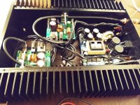
Update to post #305 above: I liked this amp enough to rebuild it in a nicer case, and do a clear job on assembly. It could still use a few finishing touches: inline mains fuse, power-on LED, and some right-length black screws for actual LM3886DR mounting. But it's way better than it was. Sorry for the lousy pics; there wasn't much light and I don't like flash photography, so opted for noisy low-light settings instead (except for the rear-end pic, I settled for flash on that one).
Tom, my condolences to you and your family.
Tom, my condolences to you and your family.
Attachments
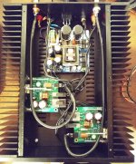
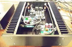
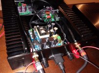
I like the slim form factor. That's a pretty nice desktop amp there. Those are some rather phallic mounting screws for the LM3886es, though. If you don't have the ability to drill and tap, I'd consider self-tapping screws. Just a suggestion.
You might not need a fuse. If the IEC inlet connects directly to the SMPS, you should be OK as the SMPS has its own fuse. If you have a power switch in series, I'd add a fuse at the IEC inlet.
I'd leave it the way it is. Enjoy it! Thanks for sharing.
Tom
If you don't have the ability to drill and tap, I'd consider self-tapping screws. Just a suggestion.You might not need a fuse. If the IEC inlet connects directly to the SMPS, you should be OK as the SMPS has its own fuse. If you have a power switch in series, I'd add a fuse at the IEC inlet.
I'd leave it the way it is. Enjoy it! Thanks for sharing.
Tom
- Home
- Amplifiers
- Chip Amps
- Neurochrome LM3886DR Build