Hi DIYers,
I just got a PAM8403 amp I'm planning to use with two 4 ohm speakers.
The problem is, that after about 75% of max volume, the sound starts getting distorted.
I tried putting a resistor between the audio jack and the input signal cables.
I used a 100kΩ resistor.
That limited the loudness and removed the distortion at max volume but the speaker was very inaudible at lower volumes and at 50% volume was barely inaudible.
Is this the right way to reduce distortion?
Are there other ways?
Is the resistor value correct?
Can this resistor be replaced with an audio potentiometer which limits the signal to 75% of max value?
I want to keep the efficiency high because it will be a battery powered system.
The simple is answer is 'don't turn it up so loud'. I'm being serious. If you reduce the level so that its distortion free on 100% then you can be sure that some quieter source material will not drive the amp fully.
If you really want to use a resistive divider, then use either a pot (or preset pot) or a fixed divider consisting of two resistors. The pot or resistors DO NOT go in series with the incoming audio but should be placed across the audio feed and with a tap off to the amplifier input.
If you really want to use a resistive divider, then use either a pot (or preset pot) or a fixed divider consisting of two resistors. The pot or resistors DO NOT go in series with the incoming audio but should be placed across the audio feed and with a tap off to the amplifier input.
The pot or resistors DO NOT go in series with the incoming audio but should be placed across the audio feed and with a tap off to the amplifier input.
Can you explain this connection?
From what I understand is that I need an audio potentiometer.
Do I have to wire it up as mentioned in this tutorial?:
How to Wire a Potentiometer: 6 Steps (with Pictures) (Leg 1: Ground, Leg 2: Amp input, Leg 3: Audio input)
Yes, that is the way to wire up a volume potentiometer.
For a two channel vol pot, you need a dual track audio law (log law) potentiometer, somewhere from 10k to 100k.
With the control shaft/knob facing towards you and the three tags (6 for stereo) facing down,
the left is Signal Return (NOT ground)
the right is Signal Input,
the middle is the wiper and becomes the Signal Output.
Considering just one channel.
The signal arrives as two wires (or a coaxial). The hot wire goes to Signal Input (right tag), the cold wire goes to Signal Return (left tag).
The signal leaves as two wires. The hot wire is from the wiper (middle tag), the cold wire is from the Signal Return (left tag).
repeat for the other channel.
All your signal TWO wire connections should be either coaxial, or twisted pair, or screened twisted pair.
NEVER use a single wire for any signal !!!!!!!!!!!!
If your vol pot has a metal case, that should be electrically connected to your chassis, If it has a metal shaft, try to connect that to the chassis as well. A spring wire touching the shaft and bolted to the chassis is good enough. Rotating the shaft wll keep the contact points clean and electrically conducting.
Last edited:
That article is very badly worded (as in wrong. Terminal 3 is the input to the pot).
First picture.
Pin 1 is ground.
Pin 2 is the wiper of the control. This connects to your amplifiers input.
Pin 3 is the input to the pot. This connects to the source component (CD player etc)
Wire the third terminal to the circuit's input. Terminal 3 is the output of the pot, which means it should be wired to the circuit's input.
First picture.
Pin 1 is ground.
Pin 2 is the wiper of the control. This connects to your amplifiers input.
Pin 3 is the input to the pot. This connects to the source component (CD player etc)
With the control shaft/knob facing towards you and the three tags (6 for stereo) facing down,
the left is Signal Return (NOT ground)
the right is Signal Input,
the middle is the wiper and becomes the Signal Output.
Ok. I understand the wiring. I just have one question though.
Where does the Signal return go?
I have three pins on the audio conector. Two are for the right and left channels.
Does the signal return go to the third pin?
-----
Also, since the pam8403 board does not have an adjustable gain, is their another way to limit the output of the amplifier?
Like this (post #7). The pin numbers are actually the same as in the first picture in your link:
http://www.diyaudio.com/forums/parts/183917-potentiometer-connection-help.html#post2485832
http://www.diyaudio.com/forums/parts/183917-potentiometer-connection-help.html#post2485832
Like this (post #7). The pin numbers are actually the same as in the first picture in your link:
http://www.diyaudio.com/forums/parts/183917-potentiometer-connection-help.html#post2485832
Ok. So I understood a lot of it.
I need to connect it in Dual gang for stereo audio.
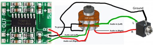
I'm attaching an image. Correct me if I'm wrong.
There are 4 grounds: 2 on the pot, one on the jack, one on the amp.
All the 4 grounds would be connected together.
The left out of pot would go to R of amp
The right out of pot would go to L of amp
I only dont know what the dashed line is.
Pin 1 is Signal it is not a ground.That article is very badly worded (as in wrong. Terminal 3 is the input to the pot).
First picture.
Pin 1 is ground.
Pin 2 is the wiper of the control. This connects to your amplifiers input.
Pin 3 is the input to the pot. This connects to the source component (CD player etc)
Pin1 connects to the input pair as Signal Return.
Pin1 also connects to the output pair as Signal Return.
Pin1 does not get connected to ground.
Referring to any of the vol pot pins as a ground is confusing.
Read his further questions: they are related to the confusion over "ground".
Last edited:
Ok. I understand the wiring. I just have one question though.
Where does the Signal return go?
The three pins in a row are ONE channel........................
Considering just one channel.
The signal arrives as two wires (or a coaxial). The hot wire goes to Signal Input (right tag), the cold wire goes to Signal Return (left tag).
The signal leaves as two wires. The hot wire is from the wiper (middle tag), the cold wire is from the Signal Return (left tag).
repeat for the other channel.
No. Considering only one channel, the vol pot has 3pins.I have three pins on the audio conector. Two are for the right and left channels.
3pins for one channel and the other 3pins for the second channel
The SIGNAL is a TWO wire connection alwaysAll your signal TWO wire connections should be either coaxial, or twisted pair, or screened twisted pair.
NEVER use a single wire for any signal !!!!!!!!!!!!..........
The signal arrives at the RCA/Phono socket on a TWO wire connection. The Flow, or Hot, is the core of the coaxial, or one coloured wire of the twisted pair. The Signal Return, or cold, is the braided screen/shield of the coaxial, or the other coloured wire of the twisted pair. Both of these copper wires MUST BE CONNECTED.
No, the input has two wires one is signal flow the other is signal return.Does the signal return go to the third pin?
the output also has two wires, one is signal flow the other is signal return.
-----
the vol pot adjusts the attenuation. That allows the fixed gain of the source and the fixed gain of the amplifier to inteface via the vol pot. The vol pot allows you to adjust the volume.Also, since the pam8403 board does not have an adjustable gain, is their another way to limit the output of the amplifier?
Last edited:
Pin 1 is Signal it is not a ground.
Pin1 connects to the input pair as Signal Return.
Pin1 also connects to the output pair as Signal Return.
P1 does not get connected to ground.
Ok. So considering just one channel. Let's say left channel.
Pin 3 recieves the hot wire from the left channel
Pin 2 is sent to L of the amp.
Pin 1 is the cold wire and it goes back to L input and also to L of amp?
Ground of 3.5 mm socket and ground of amp are connected.
I'd this correct?
The output from the source is a two wire connection. it MUST HAVE a signal flow/hot wire and it MUST HASVE a signal return/cold wire.All right.
One last thing.
The amp wires need to be twisted pair/coaxial.
The line in needs to be twisted pair/coaxial.
Thanks a lot guys.
The input to the amplifier is a two wire connection. it MUST HAVE a signal flow/hot wire and it MUST HASVE a signal return/cold wire.
In between you have the vol pot. It too has a two wire connection to it's input and has a two wire connection from it's output.
ALL the connection from Source to Amplifier are TWO wire connections. There is no exception.
If there are two Sources (as in Stereo) and two Amplifiers (as in Stereo), then you have to use two sets of TWO WIRE connections.
Oh, Bugger.Ok. So considering just one channel. Let's say left channel.
Pin 3 recieves the hot wire from the left channel
Pin 2 is sent to L of the amp.
Pin 1 is the cold wire and it goes back to L input and also to L of amp?
Ground of 3.5 mm socket and ground of amp are connected.
I'd this correct?
What are the outputs and inputs of your source and amplifier?
The 3.5mm TRS has combined the two channels' return into one connection. The Sleeve is that combined return wire.
Better if you can run the route as two sets of two wire connections, i.e. two TR plugs: T (tip) is the hot/flow and S (sleeve) is the cold/return. or use Phono/RCA, or some other plug/socket that keeps the two channels separated.
The old DIN plug was available as a 5pin DIN. It had a a pair of contacts for left channel, a pair of contacts for right channel and the 5th pin was for a separate shield/screen This 5th pin is actually the middle pin of the group. The metal shell could also carry the screen/shield. It is still available, but not popular. It is a very good way to connect adio equipment.
The 5pin DIN also got used for a tape recorder interconnect. 4 cables replaced with one cable made for simple inter-wiring.
Last edited:
Oh, Bugger.
What are the outputs and inputs of your source and amplifier?
The 3.5mm TRS has combined the two channels' return into one connection. The Sleeve is that combined return wire.
Better if you can run the route as two sets of two wire connections, i.e. two TR plugs: T (tip) is the hot/flow and S (sleeve) is the cold/return. or use Phono/RCA, or some other plug/socket that keeps the two channels separated.
The old DIN plug was available as a 5pin DIN. It had a a pair of contacts for left channel, a pair of contacts for right channel and the 5th pin was for a separate shield/screen. The metal shell could also carry the screen/shield. It is still available, but not popular. It is a very good way to connect adio equipment.
I guess there was a confusion.
I'm attaching a picture with the parts I'll be using and probably the connects are correct this time.
The amplifier is a stereo amp. The input is also stereo.
Attachments
Last edited:
don't use the 3.5mm TRS
take two signal returns from the PAM Source. One signal return gets twisted with the signal flow for a channel.
The green wire NEEDS a balck. The red wire NEEDS a black. The other signal return gets twisted with the signal flow for the other channel. These must be made up as twisted pairs or coaxials. DO NOT separate the returns from the flows. That increases LOOP AREA and big LOOP AREA increases interference.
You now have two sets of two wires fromPAM to vol pot. and two sets of wires from vol pot to amplifier. Keep those electrically separated all the way to the power amplifier.
BUT !!!!!!
the PAM has a commoned signal return. This will create a loop in your signal wiring.
You can reduce the interference on this loop by keeping the two sets of wires close together. And invoking the HBRR & HBRL from the D.Joffe article linked many times in this Forum.
Your cartoon pic looks like it is showng metal cases around the vol pots. These are the metal cases that need to be connected to chassis.
Last edited:
- Status
- This old topic is closed. If you want to reopen this topic, contact a moderator using the "Report Post" button.
- Home
- Amplifiers
- Chip Amps
- PAM8403 - Reducing input volume level to prevent distortion