I recently finished my first chip amp based on the LM3875 kit from audiosector.com and I'm delighted with the results. So much so that the amp has now replaced my beloved 34 yr old A&R Cambridge A60 which has now been relegated to the workshop.
The amp incorporates my Raspberry Pi/PiDAC combo which is the main way in which I listen to music these days and very rarely play CDs.
The PiDAC can only take digital sound from the Pi so to enable my TV audio to play through my hifi I purchased some time ago a cheap DAC on eBay. It has both a SPDIF and coax input (which allows me to connect my DVD on the rare occasion I want to play a CD directly). The SPDIF takes priority if both are presented with a signal.
I also have one set of RCA phono inputs for anything else I might want to connect to the amp, but generally speaking there won't be.
These three inputs are connected to a break-before-make 4 pole 3 way rotary switch in this order: 1. Cheap DAC, 2. PiDAC, 3. RCA with both the signal and corresponding ground from each being switched.
When I switch from position 1-2 or 2-1 I get a very loud pop in my right hand speaker. Turning the volume to zero before switching and all is quiet.
If I connect another source to the RCA inputs, switching between 2-3 in either direction does not produce any pop when the volume is not zero. If however I connect another cheap DAC of the same design to the RCA input I do get the same loud pop when switching between 2-3.
The pop occurs when the cheap DAC is powered and irrespective of whether it is being fed a signal - i.e. the source TV or DVD player can be on or off.
Clearly the issue is with this cheap DAC, which, audio wise is fine for TV viewing, but simply doesn't appreciate being suddenly connected/disconnected at the source switch.
Although I'm in the habit of turning the volume down prior to switching source does anyone have any recommendations to eliminate or significantly reduce the pop? I'd like to carry on using the cheap DAC if, for no other reason than it's built into the case.
As mentioned, the amp is based on the audiosector LM3875 kit and there is no other electronics involved. I haven't included any speaker protection for example.
Thanks in advance
Its a bit difficult to visualise all your set up, however the main reason for getting a 'pop' when switching between inputs is that the power amplifier is seeing a sudden change in DC voltage at the input.
That should give you something to work on. If any source component has any DC present at its output (even a few 10's of millivolts) then you need to AC couple the input and include a high value resistor to ground to always ensure the voltage on the output end of the cap is zero.
Also, the power amp may (unusual but it may) have a direct coupled input. Again, AC coupling is the answer. We would have to see the circuit details to determine that.
The LM3875 requires a DC path to ground (through a resistor). Some boards don't have that. If your board doesn't, then the pop could be that the DC path "disappears" as you flip the switch from Source A to Source B. That'll create a large disturbance (pop). The solution is to put a largish resistor from each input of the LM3875 board to ground. 47 kΩ or 100 kΩ would work well.
If you already have the input resistor in place, either as a resistor on the board or in the form of a volume pot, then Mooly's guess of a DC shift is probably what causes the pop.
I hope this helps. Without a schematic or drawing of your system, it's the best I can do.
Tom
If you already have the input resistor in place, either as a resistor on the board or in the form of a volume pot, then Mooly's guess of a DC shift is probably what causes the pop.
I hope this helps. Without a schematic or drawing of your system, it's the best I can do.
Tom
Mooly/tomchr - Thanks for the quick replies.
Sorry, yes I have a 50K Alps Blue volume pot in place. My initial thought was that the cheap DAC is presenting a DC offset at its output. I'm just not sure how to get rid of it.
Excuse the ignorance, but does AC coupling mean putting a small cap on the input of the amp? What type and value? Combined with a large resistor to ground - again what value? Would that combination not create a high pass filter at the input of the amp so presumably the values would have to be such that audible frequencies were allowed to pass?
Given that the issue only affects the cheap DAC can I get away with applying the change just to that switch position or should I implement it for each source? In otherwords, should I implement it for each source output before the switch or do it once after the switch and before the vol pot?
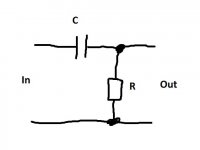
Lets look at stopping DC from a source component. This shows a series cap and a resistor to ground. Typical values would be a small 0.47uf film type cap and a 470k resistor. This ensures that whatever DC is present on the source does not get past the cap. The output is always 0.0000 volts DC.
I would try something like this first just for the DAC feed and see how you get on. Also, for interest you could try and measure any DC voltage present. It may only be a millivolt or two but you might see something and be able to compare channels.
Its also important that the power amp input doesn't see any large change in DC resistance to ground as the input is switched as that can also cause a pop.
Edit... the cap value also depends on what impedance the power amp presents and so 0.47uf may be a bit small. Used correctly, and a small and cheap electrolytic can be very suitable if you need larger values.
Attachments
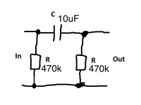
C = 470 nF, R = 470 kΩ is fine as long as the input impedance of the amp is high. In Alistair's case, it's 50 kΩ (volume pot). In his case 4.7 uF or 10 uF would be needed to ensure a low enough cutoff frequency for the AC coupling.
10 uF polypropylene would be my choice. The Nichicon Muse KZ or Muse ES series would be good choices as well.
Tom
10 uF polypropylene would be my choice. The Nichicon Muse KZ or Muse ES series would be good choices as well.
Tom
Thanks for those figures chaps. I'll need to order some components before I test that. I've got a bunch of stuff to order anyway so will add that those to the list.
Btw, I've just checked the DC offset of the spare cheap DAC I have and both channels show 7mV. This DAC showed the same symptoms when connected to the phono inputs - i.e loud pop in one channel only.
I'll update progress once I get the bits in and have tested. Many thanks in the meantime.
Btw, I've just checked the DC offset of the spare cheap DAC I have and both channels show 7mV. This DAC showed the same symptoms when connected to the phono inputs - i.e loud pop in one channel only.
I'll update progress once I get the bits in and have tested. Many thanks in the meantime.
(have you swapped the DAC outputs around, that's left to right and vice versa, just to prove that the pop transfers to the other channel)
Not as yet.... to busy enjoying the amp
")
I'll go through all that checking once I order the bits and have a spare few hours to investigate... towards the end of next week probably.
Cheers
A line level output coupling cap needs to be terminated with a resistor to ground, like Mooly's drawing. Otherwise, there will be a DC voltage on the output until it is connected to a resistive load (like the input of a preamp or power amp). Then the DC voltage will drop to zero, and you will hear a pop or thump.
Try a 100K resistor in parallel with that input on your preamp switch. If your problem is what I described, then this will cure it. If you are using the headphone output of your DAC to drive the preamp input, then a smaller resistor (like maybe 1K) would work better.
I can't imagine commercial equipment not including this feature, but who knows?
You shouldn't leave one end of the cap floating. I hacked Mooly's figure to show how I suggest implementing the circuit. Just add this to the inputs of your amp and you'll have AC coupling.
Now, if your sources have different DC offsets, you will still get a pop when you switch sources. To prevent that, you need to add the shown circuit to each of the inputs of your amp. So for a two-input stereo amp, you'll need four of these circuits. Then do the input switching between the AC coupling circuit and the volume pot.
Tom
Attachments
Components came today and a quick check on the spare DAC I have sorted the 7.3mV DC that was sitting on the outputs - not that those who offered advice will be surprised by that so thanks to you all.
Still to implement it in the amp - that's this weekend's project.
I wonder if I could wrap up the thread by posing a couple of questions:
1. Given one can never know what future sources may be plugged into the back of an amp I presume it is good engineering/design practice to always include such ac coupling components as described by Mooly et al. However, is it recommended to do so on each input at the back of the amp or include it at the input to the power amp stage?
2. As mentioned in my original description I have only 3 stereo sources and I'm using a 4 pole 3 way switch as the source switch. This is so that I can switch both the signal wires and the corresponding ground wires - I'd read somewhere (possibly in this very forum) that it was beneficial to do so. Would such an arrangement have any impact on the DC offset I've been having and it's resolution?
1/ I'm going to say that as a generalisation, both preamp and the power amp should each be AC coupled at their inputs. If you use a switching arrangement as you describe (not the grounds bit though) then each input should be treated separately and each have its own cap (and resistor to ground) rather than just one cap at the preamp input. Why so. Because one cap would still cause pops if there were DC present on any input, and it would do that because the cap would see a sudden step change in voltage as the switch operated. Defining each input from the start ensures they are all at zero volts and so that is what the switch and preamp input see.
2/ Its not common practice to switch grounds. If it were not done correctly then there is a possibility of a ground floating momentarily as the switch operates causing more than just a small pop.
2/ Its not common practice to switch grounds. If it were not done correctly then there is a possibility of a ground floating momentarily as the switch operates causing more than just a small pop.
Thanks for the quick reply Mooly.
1. As I thought but good to have confirmation from someone with a tad more experience than myself.
2. I'll try and find a link to the reference that led my to the ground switching. It gave me the impression that it was a fairly common practice.
1. As I thought but good to have confirmation from someone with a tad more experience than myself.
2. I'll try and find a link to the reference that led my to the ground switching. It gave me the impression that it was a fairly common practice.
I've never seen an amp with switched ground on the input selector.
AC coupling is a good practice. It's not always followed as some believe it negatively affects the sound quality. As long as you use a coupling cap with polypropylene dielectric or a good electrolytic cap, such as the Nichicon Muse ES or KZ series, you won't impact the circuit performance.
Tom
AC coupling is a good practice. It's not always followed as some believe it negatively affects the sound quality. As long as you use a coupling cap with polypropylene dielectric or a good electrolytic cap, such as the Nichicon Muse ES or KZ series, you won't impact the circuit performance.
Tom
Thanks guys. Annoyingly, I cannot find the article about switching the ground. I'll keep looking.
Last night I was pondering the coupling issue and wondered if the same result could be achieved by replacing the cap/resistor combo with a 1:1 transformer. Aside from the cost implications, what would be the likely audio implications?
I presume you could use different winding ratios to increase/decrease incoming signal for some 'free' gain
Transformers don't like to see any DC because it shifts the operating point of the transformer making it prone to saturation and distortion.
Look up B-H curves for transformers.
Also, although transformers won't pass DC, they will still pass a sudden shift in DC seen at the input as a thump or click.
Look up B-H curves for transformers.
Also, although transformers won't pass DC, they will still pass a sudden shift in DC seen at the input as a thump or click.
- Status
- This old topic is closed. If you want to reopen this topic, contact a moderator using the "Report Post" button.
- Home
- Amplifiers
- Chip Amps
- Loud pop when switching sources