Setup
This is my set up
input from rca to tone and tone to amp.
then from amp to speaker protection ans then output.
This is my set up
input from rca to tone and tone to amp.
then from amp to speaker protection ans then output.
An externally hosted image should be here but it was not working when we last tested it.
Please check my set up if u can figure out.
1. RCA to TOne
2. tone to Amp
3. THen Speaker protection to output.
1. RCA to TOne
2. tone to Amp
3. THen Speaker protection to output.
An externally hosted image should be here but it was not working when we last tested it.
You've attached links to images stored on another server, somewhere. Inevitably the links will break, the hosting service will shutdown, or some other calamity will occur that will make the images disappear, removing context from the thread.
If you attach the pics directly to your post, as AndrewT requests, then the images will stay with the thread for as long as diyaudio is around.
If you attach the pics directly to your post, as AndrewT requests, then the images will stay with the thread for as long as diyaudio is around.
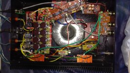
Are the input RCA jacks isolated from the chassis? It's difficult to tell from the pic.
There is a PCB assy that is floating in the air. Are there leads/circuits on the bottom of that PCB that are maybe touching conductive parts of the board underneath it?
The input signal leads cross over the toroid and a couple of EI transformers. I can't tell if the EI transformers are active or not but it may help to route those input signal leads away from the transformers.
Yes, RCA are not isolated from chassis. I think no board is floating in air. It's placed on spacers. EI xformers are active. I think EI xformer will affect both amps not one. And noise is from one amp only. If I remove ground point on input of the amp with no noise then noise gets transferred from noisy to one whose ground I remove at amp input.
I see lots of twisted, or close coupled, pairs. But I also see some "single wires".
What are they?
The input RCAs must be insulated from the Chassis.
The barrel of the RCA is part of the Input Signal wiring. This part of the Signal wiring must not be connected to the Chassis. RCA wires (two per channel) go straight to the Receiver input pads/pins, either as twisted pairs, or as coaxials.
The full set up is 2.1 lm3886 based system. The scheme is
1. Two core shielded cable is used from rca to tone control. At RCA end shield of cable has been used as common for ground. Both -ves from rca are connected to shield wire. This three input goes to tone control which has 3 pins for input. Tone output has 3 pins two for each amp and one ground. Each amp is receiving two wires (signal+ground) from tone control output. Also three wires go to subfilter two for signal and one for ground.
2. Each amp is receiving two wires of power supply from from main psu. And at output of each amp signal is going to speaker protection. Also output ground from each amp is connected to ground on main psu. For subamp, two wires go to subamp from sub filter. Both subfilter and tone control are powered by a small psu (getting power from main toroidal xformer). Speakers and subwoofer protections are powered by a another small EI xformer.
3. After protections outputs go to final terminals connected to spekaers and subwoofer. The grounds of output terminals are connected on main psu.
4. There is another small EI xformer powering the switch.
Now I hope everything about the layout is clear.
Long reply, but it does not answer the question.The full set up is 2.1 lm3886 based system. The scheme is
1. Two core shielded cable is used from rca to tone control. At RCA end shield of cable has been used as common for ground. Both -ves from rca are connected to shield wire. This three input goes to tone control which has 3 pins for input. Tone output has 3 pins two for each amp and one ground. Each amp is receiving two wires (signal+ground) from tone control output. Also three wires go to subfilter two for signal and one for ground.
2. Each amp is receiving two wires of power supply from from main psu. And at output of each amp signal is going to speaker protection. Also output ground from each amp is connected to ground on main psu. For subamp, two wires go to subamp from sub filter. Both subfilter and tone control are powered by a small psu (getting power from main toroidal xformer). Speakers and subwoofer protections are powered by a another small EI xformer.
3. After protections outputs go to final terminals connected to spekaers and subwoofer. The grounds of output terminals are connected on main psu.
4. There is another small EI xformer powering the switch.
Now I hope everything about the layout is clear.
nor confirm that your input wires meet thisBut I also see some "single wires".
What are they?
The barrel of the RCA is part of the Input Signal wiring. This part of the Signal wiring must not be connected to the Chassis. RCA wires (two per channel) go straight to the Receiver input pads/pins, either as twisted pairs, or as coaxials.
Disconnect both RCAs from the chassis. Temporary floating RCAs will do until you can get the insulating washers and drill bigger holes to suit the shouldered washers.
I think I see green grey brown yellow and red single wires. The green and grey may be coaxials, which are two wire connections, IF CONNECTED AT BOTH ENDS.
I think I see green grey brown yellow and red single wires. The green and grey may be coaxials, which are two wire connections, IF CONNECTED AT BOTH ENDS.
The amp output should go to the speaker terminals. That would be a twisted pair to each speaker terminals pair.
The amp inputs are :
a.) signal inputs, left and right . each of left and right are a coaxial, requiring 4 pads/pins for connections
b.) power input, for a dual polarity supply you need a twisted triplet from PSU to each amplifier.
There are NO SINGLE wires in any of a.) or b.)
The amp inputs are :
a.) signal inputs, left and right . each of left and right are a coaxial, requiring 4 pads/pins for connections
b.) power input, for a dual polarity supply you need a twisted triplet from PSU to each amplifier.
There are NO SINGLE wires in any of a.) or b.)
- Status
- This old topic is closed. If you want to reopen this topic, contact a moderator using the "Report Post" button.
- Home
- Amplifiers
- Chip Amps
- Hmmmmm Noise in One speaker