Yours is shipping today as well.
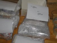
As of tomorrow, all US and Canadian orders are shipped out. There are still some international left to be done, but as I provided substantial discount on shipping those (my actual mailing cost is about $50-60 CAD), I left them for last.
Also had some problem with locating those 1/4" plastic bushing for shaft extenders, but hope to get them today.
Peter Daniel said:Yours is shipping today as well.
As of tomorrow, all US and Canadian orders are shipped out. There are still some international left to be done, .....I left them for last.
Also had some problem with locating those 1/4" plastic bushing for shaft extenders, but hope to get them today.
I cannot wait!
More than 1000k away and last to receive a shipment!
Hope those extenders are not too floppy

Peter Daniel said:It's shipping out today
Thanks Peter, now I'm a happy man!!
It looks like some of you might have already receive the chassis, so here some pointers as to assembling the amp.
I didn't drill the holes in side panels and in the 2 brackets supporting PCB; 400 and 600 holes to be drilled was beyond my scope.
The mounting holes for side panels are spaced exactly 1.00" from front and back and 0.60" from top and bottom. I would recommend 0.18 hole dia, but if you have problems with position it properly, you might go for bigger hole size, it doesn't really matter.
There are 3 holes to be drilled in mounting bracket (2.9 x 0.5 aluminum plates). Allt the holes should be positione centrally (widthwise). The one in a center is 1/8 and it's for a screw that attaches it to the copper piece. Two other holes are spaced exactly 1.125 from the center and should be tapped for #4-40 screws.
All hardware is supplied. Plastic standoffs are for PCB mounting (to those brackets). There are two #6 non magnetic screws to mount chips. I didn't provide any washers. If you think they needed, make your own choice here. I'm not using any washers.
There are 4 screws with integrated washers, those are to atach side panels to mid panel. All the other assembly is pretty much self explanatory. I recommend to retap all holes, to provide better electrical continuity between chassis parts. There are 4 sizes of taps used: 4-40, 6-40, 8-32 and 10-32.
Attach the wire to power the LED, before mounting rectifiers PCB, as later it's very hard. I'm using 68k resistor to provide voltage drop to the LED. The board doesn't have separate pads for that purpose (for some reason we didn't thought about it), so use your imagination.
I also forgot to add setting hole for the pot. You might drill it yourself, or simply brake off the notch on the pot.
The Grayhill switch has to be adjusted for 4 position operation. There are two stop pins that had to be inserted in appropriate holes. One pin goes into the hole that is placed right at the groove (in threaded part of the bushing), second pins is placed 4 spaces clockwise (from first one).
There are 2 decks and two poles, so you can switch input and ground (for each channel) separately.
Last position can be connected to the signal ground and used for muting (without a need to turn off the pot).
Shaft extenders mount to pot and switch with those plastic tubes. First you knock in the shaft (for appropriate depth) and later press fit into switch and pot shafts. This method does not provide rock solid connection, and when you force it one way, the knob will move through, but when you get use to operate it properly, you will not experience any problems.
After putting aeverything together (including wooden side panels) , you might readjust front and rear panel mounting screws to loosen up the tention on front panel, which maybe too hard to lift up.
I did not provide the ground attachment point on the chassis, and it's up to you what to use. In one example, I just didn't provide insulated washers on the ground binding posts, and it worked fine. You may only take the mains ground from AC socket and attach to the chassis. You may additionally run wires from CHG point on the PCB and attach it to the chassis as well. You might use 10 ohm resistors (or thermistor) to prowide some isolation between circuit and chassis grounds.
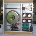
I guess I covered the basics and here the pic of the bottom side showing all power connections. It's very easy and straightforward process. Strat from amp PCB and run the wire through the hole in mid panel, choose proper length, cut and attach to rectifier's board.
Happy building
I didn't drill the holes in side panels and in the 2 brackets supporting PCB; 400 and 600 holes to be drilled was beyond my scope.
The mounting holes for side panels are spaced exactly 1.00" from front and back and 0.60" from top and bottom. I would recommend 0.18 hole dia, but if you have problems with position it properly, you might go for bigger hole size, it doesn't really matter.
There are 3 holes to be drilled in mounting bracket (2.9 x 0.5 aluminum plates). Allt the holes should be positione centrally (widthwise). The one in a center is 1/8 and it's for a screw that attaches it to the copper piece. Two other holes are spaced exactly 1.125 from the center and should be tapped for #4-40 screws.
All hardware is supplied. Plastic standoffs are for PCB mounting (to those brackets). There are two #6 non magnetic screws to mount chips. I didn't provide any washers. If you think they needed, make your own choice here. I'm not using any washers.
There are 4 screws with integrated washers, those are to atach side panels to mid panel. All the other assembly is pretty much self explanatory. I recommend to retap all holes, to provide better electrical continuity between chassis parts. There are 4 sizes of taps used: 4-40, 6-40, 8-32 and 10-32.
Attach the wire to power the LED, before mounting rectifiers PCB, as later it's very hard. I'm using 68k resistor to provide voltage drop to the LED. The board doesn't have separate pads for that purpose (for some reason we didn't thought about it), so use your imagination.
I also forgot to add setting hole for the pot. You might drill it yourself, or simply brake off the notch on the pot.
The Grayhill switch has to be adjusted for 4 position operation. There are two stop pins that had to be inserted in appropriate holes. One pin goes into the hole that is placed right at the groove (in threaded part of the bushing), second pins is placed 4 spaces clockwise (from first one).
There are 2 decks and two poles, so you can switch input and ground (for each channel) separately.
Last position can be connected to the signal ground and used for muting (without a need to turn off the pot).
Shaft extenders mount to pot and switch with those plastic tubes. First you knock in the shaft (for appropriate depth) and later press fit into switch and pot shafts. This method does not provide rock solid connection, and when you force it one way, the knob will move through, but when you get use to operate it properly, you will not experience any problems.
After putting aeverything together (including wooden side panels) , you might readjust front and rear panel mounting screws to loosen up the tention on front panel, which maybe too hard to lift up.
I did not provide the ground attachment point on the chassis, and it's up to you what to use. In one example, I just didn't provide insulated washers on the ground binding posts, and it worked fine. You may only take the mains ground from AC socket and attach to the chassis. You may additionally run wires from CHG point on the PCB and attach it to the chassis as well. You might use 10 ohm resistors (or thermistor) to prowide some isolation between circuit and chassis grounds.
I guess I covered the basics and here the pic of the bottom side showing all power connections. It's very easy and straightforward process. Strat from amp PCB and run the wire through the hole in mid panel, choose proper length, cut and attach to rectifier's board.
Happy building
Attachments
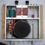
And here's the top view. As you see, I used switching attenuator. It consists of 10k Vishay S102 in parallel with 10k AN tantalum in series with a signal. The Sonic Frontieers attenuator (50 k with Holcos) provides shunting action. So basically, I have a fixed and not adjustable, series element (5k).
This configuration worked well for me in a past. BG caps had removed sleeving. I used here Apex Jr. toroid (Definitive Technology). Transformer was modified to provide double secondaries. It works and sounds very good.
There are 2 extra holes in copper heatsink, and they are used to run the wires between channels.
Attachments
assembly?
Peter,
I didn't realize we were going to have to do all this assembly...
from the way the parts were packaged, i thought i could just pop
it in the microwave - on high for about 10 minutes, and it would come out done!!
-------------------------------------------
seriously though... how do i re-tap without stripping the holes?
Should i just see if assembly goes smoothly without re-tapping first?
Thanks once again for such a great job!
m.
The assembly will go smoothly without any retaping. I recommend retaping just for striping some anodising and improving electrical contact between metal panels for improved shielding effect. It's not necessary, but it may work better after it's done.
As you tight the screws, the heads will strip anodising, you need some stripping action on threads, inside the hole; that's what retapping will do.
As you tight the screws, the heads will strip anodising, you need some stripping action on threads, inside the hole; that's what retapping will do.
Chassis Layout
Hi Peter
I have a question about general chassis layout which has been stimulated by seeing your excellent work.
It seems that there are always compromises when laying out a chassis in order to get short signal paths, air circulation, good grounding and low stray fields...all to get low noise and hum.
When you have a large chassis and/or an outboard supply it is easy to meet all of these requirements. In a small single chassis with a passive preamp built in things seem to get tricky real fast.
With your chassis the trannie is well isolated from signal wires and circuitry however the incoming AC runs right next to the pot.
I guess that I am wondering how critical it is to keep the AC away from the circuit. In my own amp which is just to the parts layout stage, my Par-Metal chassis is about the same overall dimensions as yours but I am stuggling over keeping AC away from the other wires while still keeping the trannie isolated.
Any ideas about this? Perhaps it is not as big deal as I imagine since you obviously have met with success
Best,
Paul
I was also debating the close proximity of AC wires to the attenuator. Bear in mind that with a regular pot the distance is a bit more.
One solution in creating more isolation would be adding L shape bracket made of aluminum, steel or copper and attaching it with 2 standoofs to a side panel. This way one can provide some isolation between AC wires and a pot.
Another approach might be a steel jacket (grounded) over the AC wires. Reading Madrigal literature one can learn that in their CD transport, they run AC wires from one PS tower to the other in a metal tube (across the transport area).
That said, I was already listening to this amp and didn't observe any ill efect of existing layout and AC wires proximity. Usually the potentiomenters are already in metal housing (Nobel is), so this is even less critical.
Peter,
The chassis arrived recently, and is very well done. And those knobs are truely excellent.
I am a bit curious where the wood stock came from, given the embossed lettering on one side.
And the copper "plate" looks and feels much more like a copper ingot.
Thanks for putting this group buy together.
The chassis arrived recently, and is very well done. And those knobs are truely excellent.
I am a bit curious where the wood stock came from, given the embossed lettering on one side.
And the copper "plate" looks and feels much more like a copper ingot.
Thanks for putting this group buy together.
Jesus this is a nice chassis!!
Peter,
I received mine and worked on it all day friday. Only thing I'm missing is the fuse (mine are too big) to power it on.
I just wanted to say a big thanks, it looks much better than in the pictures. The finish of the aluminum is first rate. I kept worrying about scratching it.
Some advice to fellow buiders:
It is cramped in there. Make sure you attach all the wires to the boards beforehand, and: make sure they are long enough! I had to rotate the switch to reach some of them.
I only cut a few corners. I didn't install the LED. I just forgot about it. I also didn't screw the chip boards to the base, they are only held by the chip screw, the wires underneath provide enough support.
Only thing I didn't like was the wires going from switch to volume pot. I was worried they'd pick up EMF, so I wrapped them with aluminum tape and isolated them with shrink wrap before stuffing them underneath the copper plate.
Without the lettering, it looks like a toy amplifier. I really like it.
[BTW, you forgot to send your custom speaker bindings. No sweat, I used something else.]
- Status
- This old topic is closed. If you want to reopen this topic, contact a moderator using the "Report Post" button.
- Home
- Amplifiers
- Chip Amps
- Chassis for a group order of non-inverted GC kit?