A microsecond of overvoltage will destroy a semiconductor and no fuse can open fast enough to protect one. Perhaps a cap or two was damaged also..?
That is what I initially thought. The chip is available on Ebay for less than 2 dollars, maybe locally also. A microsecond eh? Did not know that.
However I will continue trying to troubleshoot the circuit as is, using the powerful pink noise input and a voltmeter on the powered up circuit. I will have to solder the input wires now, which is a task.
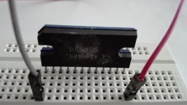
Referring to the circuit diagram here it is not too difficult to identify the components after all, starting with the capacitors. The rough diagram on Drawing tool copied here shows the components I have identified. Firstly there is the bootstrap capacitor connected across 2 and 3. Then there is the output capacitor connected between pin 2 and the output. There are also the capacitors connected between Pin 7 and the output (ground) .
It's okFire it up and listen. If it sounds funky, assume bad caps and replace them all..
I wouldn't mind if it sounds "funky" as long as it "plays that funky music right."
")
Few questions:
-Testing caps - remove from board to test?
-The power caps would be C5 and C6? Oh wait there is a huge cap connected between the diodes and the pin 1 circuit path. It looks fine, though.
Board Trace paths
Diagram showing:
Pin 1, 2, 3, 7 and the capacitors they connect to as identified on the board, this is for one channel only. Not too difficult after all.
For example Pin 2 and 3 are connected using a bootstrap capacitor whatever that is, C7, and pin 7 is connected to output ground using the C6 capacitor.

There is a large capacitor connected what seems like the diodes, but it looks fine.
Diagram showing:
Pin 1, 2, 3, 7 and the capacitors they connect to as identified on the board, this is for one channel only. Not too difficult after all.
For example Pin 2 and 3 are connected using a bootstrap capacitor whatever that is, C7, and pin 7 is connected to output ground using the C6 capacitor.
There is a large capacitor connected what seems like the diodes, but it looks fine.
Last edited:
From looking at the pic of the board that you're working on, most, if not all of the electrolytic caps are rated at 16 volts. If the power supply was 120 v.a.c. @ 12 volts out and it was fed 220 v.a.c., it's very possible the voltage surge went to 24 volts at least! Just some food for thought..
Also, if the unit is 10 yrs. old or older, electrolytic capacitors dry out over time. The Mylar/Poly caps should be fine but consider replacing all of the electrolytic types..
If you want to play Midnight Baseball, use an ohm meter and check every electrolytic and look for any reading under say.. 2000 ohms with the chip removed. If so, assume a bad cap. It suks putting in a new amp chip and watch it go up in smoke..
Just my opinion..
Good Luck!!
Last edited:
From looking at the pic of the board that you're working on, most, if not all of the electrolytic caps are rated at 16 volts. If the power supply was 120 v.a.c. @ 12 volts out and it was fed 220 v.a.c., it's very possible the voltage surge went to 24 volts at least! Just some food for thought..
That's what I was also thinking, after my new found knowledge (or refreshing of memory) about capacitor ratings. Something had to give. Also, you have not commented about the unusually high resistances across some of the chip pins.
Also, if the unit is 10 yrs. old or older, electrolytic capacitors dry out over time. The Mylar/Poly caps should be fine but consider replacing all of the electrolytic types..
My first thought was why on earth include capacitors that will only last 10 years or so? Some of the equipment I am around is more than 30 years old. It's OK for PC speakers, but I wonder about critical applications like aircraft:
Film Capacitors for Military & Aerospace Applications | Aerovox
If you want to play Midnight Baseball, use an ohm meter and check every electrolytic and look for any reading under say.. 2000 ohms with the chip removed. If so, assume a bad cap. It suks putting in a new amp chip and watch it go up in smoke..
Do you mean with the chip removed or the capacitor removed?
Further testing:
I hooked up the 3.5 mm jack to an old phone running the pink noise signal and tested the signal up to the capacitor next to the input pin. The signal was good on one side of the capacitor but barely noticeable on the voltmeter on the chip input pin.
Plan:
The plan is to remove both capacitors and test for resistance and how long they hold the charge. Depending on this test, replace and test. In any case the chip only requires 1 cap on the input side so I can maybe hook this up and test off the board. Next the output.
This video seems to show the same board being repaired.. no info on the chip though.
Removed Capacitors
I bought a new soldering iron, one with a sharp tip and easier to handle, and removed the two capacitors, the one next to input and the bootstrap one.
The capacitors got quite hot, and removing the items was difficult without pliers, solder solidifies so quickly when the heat is off for a second. Would the heat have damaged the caps?
Next step was to find a way to test the capacitors using an analog multimeter, and I found such an instruction here:
5 Ways to Test a Capacitor - wikiHow
Looking at the easier one, first the ability to hold a charge, connecting the capacitor to a 9V battery and then checking the voltage after the battery was removed gave the following results:
2.2 uf capacitor: to be tested
4.7 uf capacitor : Connected for 1 minute: showed 1 volt slowly decreasing.
Last edited:
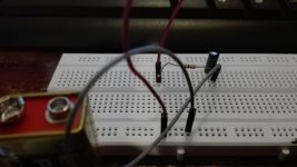
Testing on breadboard
Testing the capacitor using the breadboard, 10K resistor, and 9 V battery:
The capacitor is charged for 15 seconds, then multimeter is connected (V)
2.2 uf capacitor: shows about 6V then decreases rapidly
4.7 uf capacitor : shows the full 9 volts or so and decreases
Apparently the 2.2 is not holding charge, not upto spec, whereas the 4.7 is. The 2.2 is the input cap for the chip.
Next step is to replace it with a brand new 2.2 and do the pink noise test.
Attachments
Replaced the 2.2 and 4.7. Need to test - voltage across input and ground and output and ground? Will this burn the chip? Still no sound output.
Will resolder input and output wires and have one more go.
The voltmeter is sensitive enough to respond to pink noise output from the phone directly, so it should be able to show the signal in any other part of the circuit.
Will resolder input and output wires and have one more go.
The voltmeter is sensitive enough to respond to pink noise output from the phone directly, so it should be able to show the signal in any other part of the circuit.
More tips here:
Troubleshooting & Repair Guide
Troubleshooting & Repair Guide
7.0 Opamp Circuits There is not much that can go wrong with an opamp circuit. Most linear circuits (as used in preamps) have one thing in common - the two inputs should be at almost exactly the same voltage, and so should the output.
9.0 Removing Dead Components Once you have determined that a component is dead (or is probably dead), you need to remove it from the PCB. Never attempt to just heat the leads and prise them from the board, and resist the temptation to use a solder sucker (or solder wick) to remove the solder prior to prising the component out. This will nearly always result in damaged PCB pads and tracks. It is far better to use a very slim cutter, and cut off the legs first
OK so power up with 9V results in DC current at output terminals of the board, Left 3V and right about 9V or so, maybe less. Something is very wrong here, and I am now on the search for the shortest path to a solution:
1) Remove chip from board and test it on a breadboard. Removing without applying much heat is essential, maybe I can saw out the solder connections.
2) Replace all the output electrolytic capacitors
3) Outsource. But I already tried that and was told it cannot be repaired.
Tomorrow I decide.
1) Remove chip from board and test it on a breadboard. Removing without applying much heat is essential, maybe I can saw out the solder connections.
2) Replace all the output electrolytic capacitors
3) Outsource. But I already tried that and was told it cannot be repaired.
Tomorrow I decide.
- Status
- This old topic is closed. If you want to reopen this topic, contact a moderator using the "Report Post" button.
- Home
- Amplifiers
- Chip Amps
- Repair and re-use PC speaker amp circuit?