I purchased the LME49810 Top Audio Power Amplifier Kit Board Mono 400W DC Serve (Servo) from LME49810 Top Audio Power Amplifier Kit Board Mono 400W DC Serve | eBay
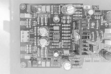
I'm going to use it to drive a Extended low-frequency sub (ESP Project 48a) while I use the MyRef LM3886 for the main amp. However I have no idea where the supply voltages are to be connected to this LME49810 board. Here's what it looks like (pls see attachment.)
FYI:
I plan to use the following Xfr and use an 8ohm sub-woofer (JBL GTO1214D 12-Inch Die Cast Dual Voice Coil Subwoofer)
Pry: 2x120 VAC @ 50 Hz
Sec: 55-0-55 VAC @ 4.54 A = 500 VA
Sec: 60-0-60 VAC @ 0.25 A = 30 VA
Capacity: 530 VA
Attachments
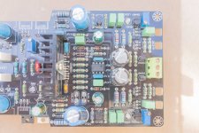
I have no idea where the supply voltages are to be connected to this LME49810 board.
It's likely that the 3 pin connector gets DC voltage that is Zener regulated down to +/- 15V for the op amp.
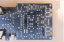
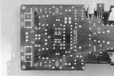
The other connector is for the power amp rails, up to +/- 60VDC. Can you post a photo of the bottom of the pcb?
You do need a schematic and other docs.
Last edited:
I doubt Chinese vendors even know what they are selling. That fellow sells shoes, handbags and electronics etc. They are just suppliers I guess. And they are on a month long vacation owing to Chinese new year.
The LME49810 amp usually requires dual supplies (one for LME49810 and another for the current amplifier/power-transistors). And there should be a difference of 5v between these supplies. I guess I don't know how to provide power to LME49810. The power to power-transistors is +/-Vcc. Could they be using a voltage divider to power LME49810 from the power-transistor supply?
Here's the reverse side (I tried to clean with alcohol but it didn't work).
Attachments
Last edited:
Electrical Characteristics (in Chinese English; if it helps):
Work status: type A and B (according to the need to adjust into the CPI)
Output power: 400W (4ω) <* V = ± 60v
Operating voltage: the voltage drive level Recommended ± 65V; current output ± 55V, the current output level voltage is always lower than the voltage drive level voltage of 5V; speaker protection voltage AC20-24V, working current <100MA available to the speaker protection circuit
Input interface: mono signal input
Output Interface: mono speaker output
Power mode: dual power mode, the voltage drive and current power output level to separate power supply.
PCB size: 298.5x 93 mm
What's include?
XD 400W Mono LME49810+2SA1930/2SC5171 Class AB
Last edited:
I see there are two or more +/-15V zener diodes connected to TL071. Is it possible they are use to convert from +/-60V to +/-15V? Because the current to LME49810 is very low, I guess there are using the same supply to power TL071. Those transistors and LEDs still make me curious.
Is it possible they are use to convert from +/-60V to +/-15V?
Yes, it's possible, and even likely. What resistors feed them?
Hi varun21,
...any progress?
I was asked by a friend for an opinion for the AmpModule from Ebay
LME49810 Top Audio Power Amplifier Kit Board Mono 400W DC-Servo
so I found this usefull thread
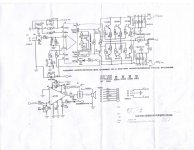
first I would like to thank you for posting the shematic
it was a big help for me!!!
-----------------------------------
OK, lets see a little more the shematic
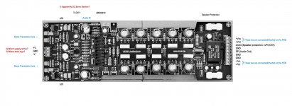
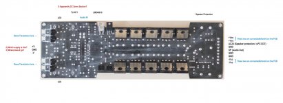
Power supply for output stage, auxiliary secondary for speaker protection and speaker connections
connector COM101:
-1,2 Unregulated Negative Power supply for output stage
-3 GND from Power supply for output stage
-4 GND for Speaker OUT
-5 Speaker OUT
-6 "GND" from auxiliary secundar (28-35VAC) for speaker protection
-7 from auxiliary secondary (28-35VAC) for speaker protection
-8,9 Unregulated Positive Power supply for output stage
Additional unregulated Power supply for LME49810
Why uregulated,
...we have very good shunt regulator for LME49810 on-board
and LME49810 has excellent PSRR
so we dont need regulated power supply, unregulated will be just fine!
connector COM102:
-1 Positive Power supply for LME49810
-2 GND from Power supply for LME49810
-3 Negative Power supply for LME49810
This Power supply (for LME49810) must be at least:
=sum(5V output stage and drivers voltage drop
+ cca 5-7V LME49810 internal VAS and pre-drivers sections, Baker clamp circuit voltage drop
+ cca 3-5V LME49810 Shunt power supply regulations)= cca 10-15V
greater then Power supply voltages for output stage, so we can benefit from max output voltage swing and max achievable output power.
If we dont use additional power supply for LME49810,
which is (+/-)15VDC grater then power supply voltages for output stage (+/-) V_out stage,
we can simply leave COM102 unconnected.
Shunt regulator for LME49810 power supply is then powered from (+/-) V_out stage power supply
thru diodes D301/302 but we lost cca 15V of output voltage headroom
and so we ending (not happy") ) with lower achievable maximum output power.
) with lower achievable maximum output power.
Example1, we have PSU with:
(+/-) 55VDC (40-0-40VAC secondary, several amperes, or tot VA)
(+/-) 70VDC (50-0-50VAC secondary, at least 200mA)
28-35VAC auxiliary secondary for speaker protection with 24VDC rele
max output speaker voltage swing is then cca 105Vpp with max 170Wrms/8R0
or 300+Wrms/4R0
Example2, we have PSU with:
(+/-) 65VDC (46-0-46VAC secondary, several amperes, or tot VA)
and with no additional secondarys
voltages on power supply pins LME49810 will be then cca (+/-) 60-62VDC
with max output speaker voltage swing cca 90-95Vpp with max 140Wrms/8R0 or cca max250Wrms/4R0
and we lose several output headroom voltage and some output power
Also, we need an additional resistor from one or another 64VAC secondary to power the speaker protection power supply COM101 pin7 or icrease R205
I_protect = cca 30-50mA or even more
(look rele specifications for I_rele, I_ic is cca 10mA)
we must drop at least 15V (from 46V to cca 30V) to power COM101 pin7 ,
so we can then use 220R-390R 2W resistor or inrease R205 for that value.
--------------------------------------------
Power the module:
A. Before powering the module
1. VR101 (Vbe multi trimmer for I_bias reg) measure with ohmmeter and adjust for max reading, we will then start with minimum bias current
2. Put in series with primar one 100-150W light bulb, this will limit max PSU current
3. Put in series from (+/-) Power supply for output stage PSU to pin1,2 and 8,9 two 12-20R several W resistors,
this precaution will limit max output stage current
4. Connect dummy load 8R0 (6R-10R) on Speaker and GND pins, COM101 pin4 and pin5
5. Short connect AudioIN and AudioGND conectors
6. Mount the amp module on massive heat sink, with termo grease, mica isolators, with proper spacers between PCB and heat sink, screws...
B. Power the module
1. Connect proper all power supplys on COM101 and COM102,
2. Power ON the sistem
3. IF light bulb on primary section lights for more then 10-15sec then we must debug or PSU or PowerAMP
4. Check voltages on COM101 and COM102, measure voltage drop on 15-20R resistors current limiters on power supply (max 1,5-2VDC drop)
5. Measure voltages on R309 (or R311, or col VT303) and on R310 (or R314, or col VT304) adjust with VR301 and VR302
to read the same value but opposit polarities, take Shunt regulator volage drop cca 3V
6. Measure voltages on DW301 and DW302 (15V zeners), 14,5-15,5VDC is OK,
this is power supply for DC servo IC and it is not critical even we read on DVM some voltage unbalance
7. Connect DVM one probe to output inductor L101 (emmiter resistors side - no rele side),
other probe on one of the 10 emmiter output transistors
With VR101 then we slowly and gradualy adjust to read on DVM cca 6,5-7,5mA
R_e=0R22,
so we have
I_bias/output pair=0,007/0,22=0,03A or 30mA/output pair
Check readings on all 10 emitter output transistors, probably we will read different values,
because the output transistors are probably not matched.
Some mA differences are not critical, R_e˙s will provide even output transistors current distribution.
8. Leave amp powered for 15-20min, readjust if necessary I_bias (see 7.)
9. Power OFF the PSU, wait that the power supply voltage drop to 0V,
then discconect light bulb, resistors limiters, connect proper power supplys again, connect the speaker,
disconnect short on audio input, connect input signal from audio source or sig.gen.
10. PowerON , then take more testings or simply enjoy
IF R136 (zobell R) run hot, there are surely oscilations
but without proper equipment (sig.gen, scilloscope) we can not debug this issue,
also, we can then fine trim compensations for better stability, faster SR, larger BW, ....
LP
Dragan
...any progress?
I was asked by a friend for an opinion for the AmpModule from Ebay
LME49810 Top Audio Power Amplifier Kit Board Mono 400W DC-Servo
so I found this usefull thread
first I would like to thank you for posting the shematic
it was a big help for me!!!
-----------------------------------
OK, lets see a little more the shematic
Power supply for output stage, auxiliary secondary for speaker protection and speaker connections
connector COM101:
-1,2 Unregulated Negative Power supply for output stage
-3 GND from Power supply for output stage
-4 GND for Speaker OUT
-5 Speaker OUT
-6 "GND" from auxiliary secundar (28-35VAC) for speaker protection
-7 from auxiliary secondary (28-35VAC) for speaker protection
-8,9 Unregulated Positive Power supply for output stage
Additional unregulated Power supply for LME49810
Why uregulated,
...we have very good shunt regulator for LME49810 on-board
and LME49810 has excellent PSRR
so we dont need regulated power supply, unregulated will be just fine!
connector COM102:
-1 Positive Power supply for LME49810
-2 GND from Power supply for LME49810
-3 Negative Power supply for LME49810
This Power supply (for LME49810) must be at least:
=sum(5V output stage and drivers voltage drop
+ cca 5-7V LME49810 internal VAS and pre-drivers sections, Baker clamp circuit voltage drop
+ cca 3-5V LME49810 Shunt power supply regulations)= cca 10-15V
greater then Power supply voltages for output stage, so we can benefit from max output voltage swing and max achievable output power.
If we dont use additional power supply for LME49810,
which is (+/-)15VDC grater then power supply voltages for output stage (+/-) V_out stage,
we can simply leave COM102 unconnected.
Shunt regulator for LME49810 power supply is then powered from (+/-) V_out stage power supply
thru diodes D301/302 but we lost cca 15V of output voltage headroom
and so we ending (not happy
) with lower achievable maximum output power.Example1, we have PSU with:
(+/-) 55VDC (40-0-40VAC secondary, several amperes, or tot VA)
(+/-) 70VDC (50-0-50VAC secondary, at least 200mA)
28-35VAC auxiliary secondary for speaker protection with 24VDC rele
max output speaker voltage swing is then cca 105Vpp with max 170Wrms/8R0
or 300+Wrms/4R0
Example2, we have PSU with:
(+/-) 65VDC (46-0-46VAC secondary, several amperes, or tot VA)
and with no additional secondarys
voltages on power supply pins LME49810 will be then cca (+/-) 60-62VDC
with max output speaker voltage swing cca 90-95Vpp with max 140Wrms/8R0 or cca max250Wrms/4R0
and we lose several output headroom voltage and some output power
Also, we need an additional resistor from one or another 64VAC secondary to power the speaker protection power supply COM101 pin7 or icrease R205
I_protect = cca 30-50mA or even more
(look rele specifications for I_rele, I_ic is cca 10mA)
we must drop at least 15V (from 46V to cca 30V) to power COM101 pin7 ,
so we can then use 220R-390R 2W resistor or inrease R205 for that value.
--------------------------------------------
Power the module:
A. Before powering the module
1. VR101 (Vbe multi trimmer for I_bias reg) measure with ohmmeter and adjust for max reading, we will then start with minimum bias current
2. Put in series with primar one 100-150W light bulb, this will limit max PSU current
3. Put in series from (+/-) Power supply for output stage PSU to pin1,2 and 8,9 two 12-20R several W resistors,
this precaution will limit max output stage current
4. Connect dummy load 8R0 (6R-10R) on Speaker and GND pins, COM101 pin4 and pin5
5. Short connect AudioIN and AudioGND conectors
6. Mount the amp module on massive heat sink, with termo grease, mica isolators, with proper spacers between PCB and heat sink, screws...
B. Power the module
1. Connect proper all power supplys on COM101 and COM102,
2. Power ON the sistem
3. IF light bulb on primary section lights for more then 10-15sec then we must debug or PSU or PowerAMP
4. Check voltages on COM101 and COM102, measure voltage drop on 15-20R resistors current limiters on power supply (max 1,5-2VDC drop)
5. Measure voltages on R309 (or R311, or col VT303) and on R310 (or R314, or col VT304) adjust with VR301 and VR302
to read the same value but opposit polarities, take Shunt regulator volage drop cca 3V
6. Measure voltages on DW301 and DW302 (15V zeners), 14,5-15,5VDC is OK,
this is power supply for DC servo IC and it is not critical even we read on DVM some voltage unbalance
7. Connect DVM one probe to output inductor L101 (emmiter resistors side - no rele side),
other probe on one of the 10 emmiter output transistors
With VR101 then we slowly and gradualy adjust to read on DVM cca 6,5-7,5mA
R_e=0R22,
so we have
I_bias/output pair=0,007/0,22=0,03A or 30mA/output pair
Check readings on all 10 emitter output transistors, probably we will read different values,
because the output transistors are probably not matched.
Some mA differences are not critical, R_e˙s will provide even output transistors current distribution.
8. Leave amp powered for 15-20min, readjust if necessary I_bias (see 7.)
9. Power OFF the PSU, wait that the power supply voltage drop to 0V,
then discconect light bulb, resistors limiters, connect proper power supplys again, connect the speaker,
disconnect short on audio input, connect input signal from audio source or sig.gen.
10. PowerON , then take more testings or simply enjoy
IF R136 (zobell R) run hot, there are surely oscilations
but without proper equipment (sig.gen, scilloscope) we can not debug this issue,
also, we can then fine trim compensations for better stability, faster SR, larger BW, ....
LP
Dragan
- Status
- This old topic is closed. If you want to reopen this topic, contact a moderator using the "Report Post" button.
- Home
- Amplifiers
- Chip Amps
- Need Help With Connecting Supply to LME49810 AMP (Servo)