tle2426 noise
Hi!
So I have been playing around with a preamp based on an old Toshiba op amp. I am getting cyclic hum that is not there when i feed the circuit from outside the enclosure with two 9V inputs from my Pedal Power supply. Hum is only present on high volume positions (see the 10k pot in the preamp drawing) but it is pretty unacceptable by modern pedal standards.
Any thoughts on what's going on here in terms of how to further reduce noise on the TLE2426?
Thanks!
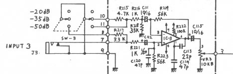
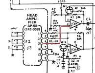
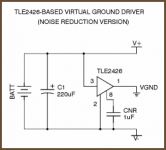
Attached is the preamp circuit as well as the second op amp shown on the main drawing. I also attached a pic of the rail splitter circuit i am using.
Hi!
So I have been playing around with a preamp based on an old Toshiba op amp. I am getting cyclic hum that is not there when i feed the circuit from outside the enclosure with two 9V inputs from my Pedal Power supply. Hum is only present on high volume positions (see the 10k pot in the preamp drawing) but it is pretty unacceptable by modern pedal standards.
Any thoughts on what's going on here in terms of how to further reduce noise on the TLE2426?
Thanks!
Attached is the preamp circuit as well as the second op amp shown on the main drawing. I also attached a pic of the rail splitter circuit i am using.
Attachments
Last edited:
My crystal ball's out for repair again. Pesky things are so unreliable. No, but seriously, it is quite impossible to tell what's wrong from what you write. What kind of 18V supply is it, how is it hooked up? Is it not overloaded, does the voltage look good? How is the unit originally powered, what kind of IEC class was it? Have you verified supply voltages at the opamps themselves?
Finally, are there any buffer capacitors on the supply voltages after the rail splitter? The circuit looks kinda skimpy, as they commonly were in the olden days. You will note from the datasheet (Fig. 17) that the TLE2426 can go unstable when loaded anywhere between about 1 and 300 nF, so at least a small electrolytic from VGND to V- is recommended.
The purpose of opamp #2 is at least twofold:
1. Provide a low-impedance output (would be kinda high after the adder otherwise)
2. Provide some more gain to achieve required levels. GBW of these very old parts wasn't great to begin with, and splitting gain between two stages means lower distortion and higher bandwidth.
I am not sure what the purpose of the FET switching is.
My crystal ball's out for repair again. Pesky things are so unreliable. No, but seriously, it is quite impossible to tell what's wrong from what you write. What kind of 18V supply is it, how is it hooked up? Is it not overloaded, does the voltage look good? How is the unit originally powered, what kind of IEC class was it? Have you verified supply voltages at the opamps themselves?
Finally, are there any buffer capacitors on the supply voltages after the rail splitter? The circuit looks kinda skimpy, as they commonly were in the olden days. You will note from the datasheet (Fig. 17) that the TLE2426 can go unstable when loaded anywhere between about 1 and 300 nF, so at least a small electrolytic from VGND to V- is recommended.
The purpose of opamp #2 is at least twofold:
1. Provide a low-impedance output (would be kinda high after the adder otherwise)
2. Provide some more gain to achieve required levels. GBW of these very old parts wasn't great to begin with, and splitting gain between two stages means lower distortion and higher bandwidth.
I am not sure what the purpose of the FET switching is.
Thanks for the feedback! Lol, and sorry for the complex inquiries. My own limited knowledge of audio systems makes me presume what you guys know to be naturally more advanced. Clearly I am having a hard time gauging the complexity of my own inquiries
 .
. The original power source on the machine is -/+14V. That's about all I can deduce. With the TLE2426, both op amps are getting -/+9V and neither is rated at drawing more than a few mA. I have verified they are both getting the 9V. I have the TLE2426 set up as in the drawing attached with a 220uF polarized and a big-ish, non-polarized 1uF. Can I put more capacitors elsewhere?
My impression is that the noise from the TLE2426 is already there as I can turn down the guitar volume, crank the pot on the Toshiba op amp and I can barely hear the beginnings of the hum. But once the second op amp is accepting the output of the first, the noise becomes very prominent. The second op amp is a JRC4558D.
Here's another inquiry... Hopefully considerably less complex so as to offset the far reaching nature of my first inquiry.
Note at the output of the preamp there's a pot to control the volume. To my untrained eye, that looks like it is not a resistor that controls the gain of the op amp in the traditional sense. Is that correct? I mean, it's not one of the resistors whose ratio dictates the gain but rather the gain of the op amp is fixed and this pot is metering the output by sending part of the signal to ground?
If I found the gain of the system to be too high, especially once the second op amp is included, how can I go about reducing the output via that pot? Can I simply change the value of the pot? I tried a 5k audio pot instead of the 10k that's specified, but I can't tell if I made a difference.
That's correct, the opamp runs at fixed gain, all the pot does is allow you to tap off a percentage of the opamp output. The value of the pot makes no difference as long as its not to low a value such that it loads the opamp.
If there is to much gain (and the opamp is clipping) then you have no option but to either attenuate the signal applied to the opamp input, or alter the feedback factor around the opamp.
If there is to much gain (and the opamp is clipping) then you have no option but to either attenuate the signal applied to the opamp input, or alter the feedback factor around the opamp.
That's correct, the opamp runs at fixed gain, all the pot does is allow you to tap off a percentage of the opamp output. The value of the pot makes no difference as long as its not to low a value such that it loads the opamp.
If there is to much gain (and the opamp is clipping) then you have no option but to either attenuate the signal applied to the opamp input, or alter the feedback factor around the opamp.
Thanks! Does anyone know what noise generated by the TLE2426 sounds like? I assume it must have an oscillating activity going on in there given it has a noise reduction pin. Is this thing overkill for powering two op amps? What are pedal manufacturers using for dual supply requirements?
There should be zero noise. Remember that the output pin of the device becomes the 'reference' point or ground in the circuit its used in. So by definition that point is clean even if the main rail has noise on it.
The noise reduction pin simply allows additional decoupling to the internal mid rail voltage reference.

(I've no idea what manufacturers use for these kind of applications)
The noise reduction pin simply allows additional decoupling to the internal mid rail voltage reference.
(I've no idea what manufacturers use for these kind of applications)
Geez, maybe I should try that rail splitter again and see what's up. I set the preamp up to run on two isolated DC inputs from the Pedal Power device. Now the two cascading op amps are whisper quiet. I'm going to use an 18V input from the Pedal Power and split it externally from my circuit with the TLE2426 and see what's what.
Its hard to say without actually being there and seeing how its all configured. Its very easy to make errors in grounding when combining virtual grounds with other circuitry.
Let me ask you this: when using a virtual ground set-upshould the shielding of the circuit (i.e. the ground going to the enclosure) be the virtual ground?
Yes, in a virtual ground set up the virtual ground becomes our point of reference, our new zero volts or ground point, and as such is treated as if it were a proper ground.
Its a fine distinction though, what is true virtual ground circuitry and what is really 'single rail' using a virtual ground to derive bias voltages. This is why its easy to make errors. You can't really combine circuitry that uses the '0 volts' point as its ground in a single rail set up with more circuitry using a virtual ground when all is fed from the same PSU.
Its a fine distinction though, what is true virtual ground circuitry and what is really 'single rail' using a virtual ground to derive bias voltages. This is why its easy to make errors. You can't really combine circuitry that uses the '0 volts' point as its ground in a single rail set up with more circuitry using a virtual ground when all is fed from the same PSU.
Interesting you should say that since i recall the worst of the noise came when i used my pedal along with a modern EL Capistan delay pedal (which is not an otherwise noisy pedal in any way) with a digital wet signal. Could what you are alluding to above be related to that I wonder? I mean in terms of the design philosophy of the EL Capistan conflicting with the virtual set-up of mine.
Hard to say for sure without seeing it all and how its all configured.
For example, if you have an 18 volt single rail circuit then that will use the '0' volts line as ground. Everything is related to that point. If you now add a virtual ground circuit (your rail splitter) to that same 18 volt supply then you now have two 'grounds'. The first is the original '0' volts point the original circuitry uses, and the second the virtual ground that is now sat at +9 volts relative to that '0' volts points. The circuitry powered from the virtual ground expects to use the +9 volts as its reference and so that means that the original '0' volts point is now dirty and contaminated when compared against the clean +9 volt point. And yet that '0' volts is 'clean' as seen by the original circuit. So there is a conflict.
Its also very easy to short out the virtual ground and the '0' volts points by thinking of them as both being ground.
- Status
- This old topic is closed. If you want to reopen this topic, contact a moderator using the "Report Post" button.
- Home
- Amplifiers
- Chip Amps
- cascading op-amps and tle2426 noise