whereas: I just noticed that my CD o/p sounded much better with LM6182 biased into class A with resistors ( CCS trial coming soon )
and whereas Nelson ( and others I'm sure ) believe that the sound quality of the first watt is the most important
and whereas I like designing balanced working amps
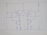
therefore I present the idea of a balanced wkg gainclone. Powered from 3 x 12.7 V batteries per channel. Perhaps using 2050's cos they sound good with batteries and can supply 5 amps. With the first watt ( or two ) biased into class A with CCS's and the o/p lifted a few volts to maintain max o/p swing.
I won't be building this one for a while, too busy on other stuff, but based on my previous experience I think this could be quite nice.
All comments welcome
mike
p.s. I drew this diagram on a train, so please make allowances
and whereas Nelson ( and others I'm sure ) believe that the sound quality of the first watt is the most important
and whereas I like designing balanced working amps
therefore I present the idea of a balanced wkg gainclone. Powered from 3 x 12.7 V batteries per channel. Perhaps using 2050's cos they sound good with batteries and can supply 5 amps. With the first watt ( or two ) biased into class A with CCS's and the o/p lifted a few volts to maintain max o/p swing.
I won't be building this one for a while, too busy on other stuff, but based on my previous experience I think this could be quite nice.
All comments welcome
mike
p.s. I drew this diagram on a train, so please make allowances
Attachments
OK that's interesting - the only thing is, in a reply to Fred Dieckmann about biasing op amps into class A scott wurcer said the following
....The question remains as to N-ness or P-ness in the direction of the CCS, you will have to experiment and determine for yourself. I did this experiment years ago on a classic Bipolar process (bad pnp) and the pnp (pull up) was better, go figure....
I will have to hope that with the chip I select the pull down sounds the best otherwise I will loose this advantage.
perhaps we will resurrect these threads if and when one of us builds one of these cct's
regards
mike
Hi Mike,
Well, it is just a matter of trying. Your circuit will work as well with a current source as with a current sink.
My circuit (in http://www.diyaudio.com/forums/showthread.php?postid=325476#post325476) already uses both current sinking and sourcing. I pressume that with LM3886 amplifiers both halves work quite well as class A output. As long as they stay in class A there will be no crossover anyway.
Steven
kafka said:>mikelm
I'm going to build such amp, but I'm wondering how much bias should I apply? 200mA per chip? Not enough? 500mA?
I want to have 5, 10W in A class.
looking at my diagram it looks like I was thinking to have about 500mA but I think starting at 200mA is a good idea.
perhaps make it possible to change the current source resistor easily so that you can try some different values.
Make sure that you use big enough heatsinks !
good luck
mike
Mike, this is such a simple test that I was thinking in making for some time that now I have the opportunity and this is it.
I'm makin' a small amp for my bench/computer.
Inverting T-network LM1875, with OPA2132 input buffer and a small unregulated (tweaked ) +/- 14V PSU.
This is a ~10W amp.
It has no case yet, it's still a bunch of aligators as connectors and it's playin' for some days now, with Visaton FR10-8 fullranges that will have an enclosure today, along with small tweeters.
Anyway, I've just took two 68ohms/3watt resistros from my parts box and put them there (this gives ~205ma biasing).
DC goes a little higher, but nothing special: 40mv.
So, music it is.
There seams to be something more goin' on around here, but it's difficult to say with these speakers.
As I have some enclosures to make today (and tomorrow), I will have no time to test this in my main system.
But I put here a challenge: who dares?
Seriously guys, try it, it's so simple...
Say what you think.
Note: the 3w resistors get very hot.
But the heatsink is cool, due to the low voltage of the PSU. This amp doesn't get hot at all.
If I use this on the final amp, I would rather take the voltage from the buffers' regulators, and not from the unregulated PSU.
IDEA: maby I will use a switch to activate or not the class-A biasing!
I'm makin' a small amp for my bench/computer.
Inverting T-network LM1875, with OPA2132 input buffer and a small unregulated (tweaked
) +/- 14V PSU.This is a ~10W amp.
It has no case yet, it's still a bunch of aligators as connectors and it's playin' for some days now, with Visaton FR10-8 fullranges that will have an enclosure today, along with small tweeters.
Anyway, I've just took two 68ohms/3watt resistros from my parts box and put them there (this gives ~205ma biasing).
DC goes a little higher, but nothing special: 40mv.
So, music it is.
There seams to be something more goin' on around here, but it's difficult to say with these speakers.
As I have some enclosures to make today (and tomorrow), I will have no time to test this in my main system.
But I put here a challenge: who dares?
Seriously guys, try it, it's so simple...
Say what you think.
Note: the 3w resistors get very hot.
But the heatsink is cool, due to the low voltage of the PSU. This amp doesn't get hot at all.
If I use this on the final amp, I would rather take the voltage from the buffers' regulators, and not from the unregulated PSU.
IDEA: maby I will use a switch to activate or not the class-A biasing!
Carlos,
I am delighted that someone has tried this idea. I look forward to hearing what you think when you can listen more clearly.
Do you think the resistor is going to be superior to a CCS ?
I currently have on my workbench 4 half finnished choke and gyrator regulated chip amps based on TDA2050.
Do you know of any reason that these should not work OK using a T network ?
If they work OK I will then try this biasing mod as well so I get to hear it myself
and then that only leaves an input buffer.....Mmm tube or 627 ?
mike
SheldonD said:Carlos: I have no doubt that the resistors get hot!
If you do your IxIxR = watts you get 27.2 watts, pretty good if the 3 watters can stand it.
When they are hot check the voltage drop ot monitor current and see what the real resistance is when hot.
Yes, but this is what I had for the value I wanted to test.
I listened for around 5 minutes LOUD AND CLEAR, then removed the resistors, listened again, then put them back, listened again.
The 3w carbon resistors got very hot, but no trace dark colour or (worse) red incandescent colour or (even worse) bang!


carlosfm said:Anyway, I've just took two 68ohms/3watt resistros from my parts box and put them there (this gives ~205ma biasing).
SheldonD said:If you do your IxIxR = watts you get 27.2 watts, pretty good if the 3 watters can stand it.
I^2.R=2.72W
but that's enough to get hot.Steven
mikelm said:Do you think the resistor is going to be superior to a CCS ?
This is quite a different situation to signal op-amps.
The resistor needs to be high wattage, I'd say 5 watts would do in most situations.
Anyway, I will test this better.
One thing that always worries me is injecting unregulated PSU noise on the output. I will test with +/- 9V regulators. For a start I can use those I have on the input buffer.
mikelm said:I currently have on my workbench 4 half finnished choke and gyrator regulated chip amps based on TDA2050.
You did well, as the TDAs have low PSRR, and this one is no exception.
Most of them are made for car audio.
mikelm said:Do you know of any reason that these should not work OK using a T network?
I don't know, try it, why not?
mikelm said:If they work OK I will then try this biasing mod as well so I get to hear it myself
Please do.
mikelm said:and then that only leaves an input buffer.....Mmm tube or 627 ?
That is your choice.
OPA627 biased to class-A between 5 to 10 ma sounds very good.
I still have to try a valve buffer, didn't have the time yet.
Anyway, I'm very "biased" to SS.
Stay clear...
I have 33ohm/11watt resistors now.
The heatsink is now... warm.
My fingers can't stay there for more than 5 seconds.
But it's a small heatsink, not intended to be used like this.
PSU voltage went down to +/-12v.
Biasing is now... 363ma.
I can't even touch the resistors, but the amp is playin' for around 10 minutes now.
I need a fan.
I have 33ohm/11watt resistors now.
The heatsink is now... warm.
My fingers can't stay there for more than 5 seconds.
But it's a small heatsink, not intended to be used like this.
PSU voltage went down to +/-12v.
Biasing is now...
363ma. I can't even touch the resistors, but the amp is playin' for around 10 minutes now.
I need a fan.
mikelm said:any impressions from that 10 minutes ?
Yes, the sound seamed to be "smoother", not what I consider better.
It can be because of the high temperature of the chips/heatsink.
The trafo was also quite warm.
I have been testing and with this amp/psu it seams that a good compromise is 120ohms (I'm using 5w resistors).
PSU voltage is... let me see... +/- 13.4v, so this is ~111ma biasing.
I'm not comparing biased and non-biased so no conclusions yet.
Also, I don't know very well the sound of these speakers.
If I have the time tomorrow I will test this on my main system, with my Epos ES11 speakers.

carlosfm said:If I have the time tomorrow I will test this on my main system, with my Epos ES11 speakers.
My modified B&W DM602 S3's are pretty wicked as well
I just poured a mixture of 3 parts sand and 1 part resin into all of the cavities in the moulded plastic baffle.
Plus more tweaks to my rebuilt cross-overs ( next to the amps )
Not to mention the full suspension using the inner tube of a bicycle tyre and a 50mm patio slab !
... ... I guess I should get some sleep...

mike
mikelm said:My modified B&W DM602 S3's are pretty wicked as well
You have those?

My Epos are easy to drive compared to those speakers.

The 602 S3 are 8 ohms but have an impedance dip in the bass at 2.8 ohms.
I know them well, it disgraces too many commercial amps, bass is not tight, they demand current.
I would recommend you to use at least two parallel LM3886s per channel, no to talk about bridge/parallel.
Gotta go to sleep now...

I have done this a slighly different way
force the same offset on both bridged amp with DC voltage on input. all you are doing in this case is mixing a Dc voltage with the signal. since both of the amps are using input that is oposite each other, in a pefect world the voltage referance does not have to be perfect, but the cleaner the better. the outputs of the amps wil l be the same so there will be nothing across the speaker however if that was not moving much im sure it would sound better
you can not assume both amplifiers will react exactly the same to a varying reference voltage with noise and voltage dips from bass etc.so it would probably be best to use a proper one rather than just a voltage devider from one of the rails. (although it worked )
what i have here is mixing DC with both of the amplifiers inputs. it is a simplified version because i have not perfected the values yet (now i see t net and IGC maybe i may be changing again!) with a bridged amp and the dc is set up right. (you will have to use a multiturn 1k or so on the reference to get 0 difference on outputs)
the actual amount of dc ofset is up to you you could have :
first watt
first 5 watts
1/2 psu volt do its all class a but only same power as 1 chip
(and i wouldnt bother with 3875 unless you heve super efficient speaker to use it with. 2x 3886 would probably be about the same power wise as 1 3875) with ur average "8 ohm" speaker
I have not double checked that though. this is still rather preliminary testing, but i have used my briangt with it (so it ends up one chan) and it seems to work. much more testing needed!
force the same offset on both bridged amp with DC voltage on input. all you are doing in this case is mixing a Dc voltage with the signal. since both of the amps are using input that is oposite each other, in a pefect world the voltage referance does not have to be perfect, but the cleaner the better. the outputs of the amps wil l be the same so there will be nothing across the speaker however if that was not moving much im sure it would sound better
you can not assume both amplifiers will react exactly the same to a varying reference voltage with noise and voltage dips from bass etc.so it would probably be best to use a proper one rather than just a voltage devider from one of the rails. (although it worked
)An externally hosted image should be here but it was not working when we last tested it.
what i have here is mixing DC with both of the amplifiers inputs. it is a simplified version because i have not perfected the values yet (now i see t net and IGC maybe i may be changing again!) with a bridged amp and the dc is set up right. (you will have to use a multiturn 1k or so on the reference to get 0 difference on outputs)
the actual amount of dc ofset is up to you you could have :
first watt
first 5 watts
1/2 psu volt do its all class a but only same power as 1 chip
(and i wouldnt bother with 3875 unless you heve super efficient speaker to use it with. 2x 3886 would probably be about the same power wise as 1 3875) with ur average "8 ohm" speaker
I have not double checked that though. this is still rather preliminary testing, but i have used my briangt with it (so it ends up one chan) and it seems to work. much more testing needed!
carlosfm said:
You have those?
My Epos are easy to drive compared to those speakers.
The 602 S3 are 8 ohms but have an impedance dip in the bass at 2.8 ohms.
I know them well, it disgraces too many commercial amps, bass is not tight, they demand current.
I would recommend you to use at least two parallel LM3886s per channel, no to talk about bridge/parallel.
Gotta go to sleep now...
Well - if you do all the things that I have described including a serious cross-over reworking to get rid of the sharp knees- you know - more like bessel like and put a Zobel on the bass unit and then take out all of the stuffing - you might be suprised not to say amazed. The dip, I think, is in the treble region and my 25watt per channel class A's seems quite happy.
I like to try and get the best out of budget gear and these speakers have really responded. My next plans are to clad the sides with marble and extend the cabinet at the back in a tapering shape.
If you have not tried putting your speakers on really heavy slabs and then suspending them on springs or an air cushion ( inner tube ) you might be in for a pleasant suprise.
I look forward to you report on the biasing in your main system
cheers
mike
- Status
- This old topic is closed. If you want to reopen this topic, contact a moderator using the "Report Post" button.
- Home
- Amplifiers
- Chip Amps
- First Watt balanced gainclone idea