peranders said:What about the noise when you have 1 M ohms source resistance?
Isn't that resistance shunted at AC by a lower resistance in this scheme?
SY said:
Isn't that resistance shunted at AC by a lower resistance in this scheme?
Yes it is, so not much worrying about that. I'd really like to find out a formula for the value of the cap. It's not just the DCFB res. that it depends on.
/Greg
The devil is in the details.
"Do you ever bother to do order-of-magnitude calculations"
Yes, when appropriate. ESR is non linear. Go read a little about what a capacitor's ESR is caused by before you throw stuff out there with seemingly little concern for credibility. I guess you don't believe in wine tasting but rely strictly on chemical analysis to differentiate wine. Who could trust anything as subjective as taste to compare wines........
It just flies in the face of common sense.
Re: The devil is in the details.
Fred (or anybody else),
Can you tell me how to calculate the value of the FB cap in the sch. above, please?
Thanks up-front.
/Greg
Fred Dieckmann said:"Do you ever bother to do order-of-magnitude calculations"
Yes, when appropriate. ESR is non linear. Go read a little about what a capacitor's ESR is caused by before you throw stuff out there with seemingly little concern for credibility. I guess you don't believe in wine tasting but rely strictly on chemical analysis to differentiate wine. Who could trust anything as subjective as taste to compare wines........
It just flies in the face of common sense.
Fred (or anybody else),
Can you tell me how to calculate the value of the FB cap in the sch. above, please?
Thanks up-front.
/Greg
Fred, you still haven't considered order-of-magnitude. Why not pick a good quality cap (not designer stuff, just something like a cap one might find in an Adcom or Rotel) and show how much the variation in ESR compares to the series resistance? I can run through it if you don't want to be bothered with such trivia.
Reality check: what's the distortion of an Adcom or Rotel? How much is from the electrolytic in the feedback loop?
Disclaimer: I use servoes, so this is an academic exercise for me.
Reality check: what's the distortion of an Adcom or Rotel? How much is from the electrolytic in the feedback loop?
Disclaimer: I use servoes, so this is an academic exercise for me.
Re: Re: The devil is in the details.
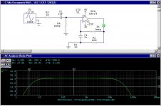
I guess I'll answer my own question. I just found out that the equivalen resistance that determines the -3dB freq. is =Rdc/gain of the amp. In the case above: Rdc=1meg The gain is 22k/1k=22, so the equiv. res (IF the AC NF res are significantly smaller than the Rdc) is 1meg/22=45k, so the f=1/(6.3x45kx1uF)=3.5Hz.
GregGC said:
Fred (or anybody else),
Can you tell me how to calculate the value of the FB cap in the sch. above, please?
Thanks up-front.
/Greg
I guess I'll answer my own question. I just found out that the equivalen resistance that determines the -3dB freq. is =Rdc/gain of the amp. In the case above: Rdc=1meg The gain is 22k/1k=22, so the equiv. res (IF the AC NF res are significantly smaller than the Rdc) is 1meg/22=45k, so the f=1/(6.3x45kx1uF)=3.5Hz.
This is in reply to Per's post. A resistor is a noise source only when it has current flowing through it. In the case of the simulation using a LM324, you are right - the 1M feedback value wasn't appropriate, not only considering noise. The 324 is a bipolar input amp with 45-250 nA bias current. The bias current and resistance result in about 45-250 mV extra offset. The offset could be cancelled out with a 1M resistor on the + input as well, but then you have 45-250 mV of steady common mode input. Not nice, either way. For a FET op amp, however, the 1M feedback resistor would be more appropriate, as the bias current is orders of magnitude smaller. A person wanting to eke out the very best noise performance could always use a somewhat smaller feedback resistor and larger coupling capacitor. I would do the calculation of noise current X resistance first, though.
I did the analysis of the network a few years back, and found to my surprise that the capacitor value was not simply a function of the RC time constant of the coupling capacitor and the unity feedback resistor. If I have time to work it out again, I'll post either the analysis equations or a spreadsheet .
I did the analysis of the network a few years back, and found to my surprise that the capacitor value was not simply a function of the RC time constant of the coupling capacitor and the unity feedback resistor. If I have time to work it out again, I'll post either the analysis equations or a spreadsheet .
About capacitor
I did some measurements on this subject today.
I did measurements on a NIGC with a LM3875.
I added the input capacitor. If I remove the
resistor from + input to ground the voltage over
the capacitor is almost equal to the rail voltage.
I did not connect the + input to anything.
The offset I measured on the output was very high
21 V.
I tried different caps in this position. A 30 uF film
and a 47 uF NP electrolytic. I could not distinguish
between either and a straight wire.
Now I have a question about the National
bpa200. They do not have an input + connection to
ground (Except before the buffer stage). How does this
work? Am I missing something? Also in a parallel
amp could the capacitor be shared by the parallelled
chips of is this not a good idea?
Thanks
Harry
Harry,
There is always some bias current flowing into (or out of, depending on the type) the inputs of an opamp. If that current has no path to ground, the input node starts to float up (or down). Use a resistor to gnd (not too large, as small as possible wrt the source resistance) and you're home free.
And yes, you can share the input cap among parallel amps.
Jan Didden
Re: Amp Feedback
one new way, for me, to deal with DC offset feedback
thanks
wrenchone said:
The circuit in the attached file labeled "A" is the one discussed in this thread so far.
The disadvantage of this approach is that C1 must be relatively large,
and it does see some reverse bias when the output swings negative.
I would try using an Oscon for C1 in circuit A,
as they are supposed to tolerate substantial reversal without ill effects.
I first learned about the Circuit labeled "B" over 20 years ago in Audio magazine.
-----------
I use this circuit ("B") in my projects almost always instead of the conventional one ("A").
one new way, for me, to deal with DC offset feedback
thanks
- Status
- This old topic is closed. If you want to reopen this topic, contact a moderator using the "Report Post" button.
- Home
- Amplifiers
- Chip Amps
- Feedback capacitor to minimize DC offset