This is a new Project of mine. Based on all information collected from this forum an all over the internet.
First of all, there’s a simple buffer stage to compensate impedances and signals. The idea here is to reduce the noise effect on further stages.
Then the LPF and the HPF, for low and mid+hi ranks. Based on Linkwitz’s Pluto design I used those filter schematics for this design. The low pass filter is set to 600Hz, a two 12dB/octave series filter are placed for this task, connected to a noninverting opAmp and an inverting configuration opAmp. Instead of doing the regular BTL circuit between two LM1875, I use them as a non inverting, and feed them with an inverted (180 degrees) signal.
SALIDA W is the output for Woofer, both LM’s have their Zobel network to prevent oscillations.
For the High pass filter, I use the same principle, based on the “24 dB/oct Linkwitz-Riley crossover”. A delay correction is used with an all pass filter. And then the signal feeds another LM1875 using the same schematic as for the BTL configuration.
The PSU is not shown, but the idea is to have them separately for each stage, as follows: Operational Amplifiers (SPLY OA), Woofer BTL Amplifier (SPLY PWR), Mid+Hi Range Amplifier (SPLY PWR2). Resistors RGND and RGND2 are used just for PCB layout purposes although RGND may be used (few ohms, like 27 or 33). The idea is to use different connecting pads for the GND power to prevent noise on the low power section.
Why three PSU, actually it can be used a single transformer, but remember that Operational Amplifiers need regulated power supply.
The other two PSU goes for this reason:
If you use all 8 ohms speakers (and tweeters, etc), then
For Mid+Hi output of 15W you need 17+17 VAC transformer.
For Low output of 40W you need 14+14 VAC transformer.
All that depends on the efficiency of your speaker system, etc. Etc. In my case I needed 30W + 15W, so a 12+12 VAC is needed instead of 14+14. I recommend you t oread “Overture™ Series High Power Solutions” that’s an application note from NS (AN-1192). Of course you can feed them with the same PSU, same values.
For a stereo version, of course you’ll need two desgins like this, for L and R channels.
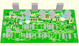
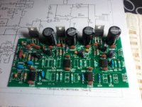
I attach the schematic, and PCB I’ve designed for this, I’ll be posting more photos as the Project goes further. I hope you like this experiment, and feel free to try it and let me know your results.
Kind Regards.
First of all, there’s a simple buffer stage to compensate impedances and signals. The idea here is to reduce the noise effect on further stages.
Then the LPF and the HPF, for low and mid+hi ranks. Based on Linkwitz’s Pluto design I used those filter schematics for this design. The low pass filter is set to 600Hz, a two 12dB/octave series filter are placed for this task, connected to a noninverting opAmp and an inverting configuration opAmp. Instead of doing the regular BTL circuit between two LM1875, I use them as a non inverting, and feed them with an inverted (180 degrees) signal.
SALIDA W is the output for Woofer, both LM’s have their Zobel network to prevent oscillations.
For the High pass filter, I use the same principle, based on the “24 dB/oct Linkwitz-Riley crossover”. A delay correction is used with an all pass filter. And then the signal feeds another LM1875 using the same schematic as for the BTL configuration.
The PSU is not shown, but the idea is to have them separately for each stage, as follows: Operational Amplifiers (SPLY OA), Woofer BTL Amplifier (SPLY PWR), Mid+Hi Range Amplifier (SPLY PWR2). Resistors RGND and RGND2 are used just for PCB layout purposes although RGND may be used (few ohms, like 27 or 33). The idea is to use different connecting pads for the GND power to prevent noise on the low power section.
Why three PSU, actually it can be used a single transformer, but remember that Operational Amplifiers need regulated power supply.
The other two PSU goes for this reason:
If you use all 8 ohms speakers (and tweeters, etc), then
For Mid+Hi output of 15W you need 17+17 VAC transformer.
For Low output of 40W you need 14+14 VAC transformer.
All that depends on the efficiency of your speaker system, etc. Etc. In my case I needed 30W + 15W, so a 12+12 VAC is needed instead of 14+14. I recommend you t oread “Overture™ Series High Power Solutions” that’s an application note from NS (AN-1192). Of course you can feed them with the same PSU, same values.
For a stereo version, of course you’ll need two desgins like this, for L and R channels.
I attach the schematic, and PCB I’ve designed for this, I’ll be posting more photos as the Project goes further. I hope you like this experiment, and feel free to try it and let me know your results.
Kind Regards.
Attachments
Last edited:
The bane of BTL circuits is the resistor network, whatever configuration it may be. Your BTL circuit is better than many implementations of yesteryear, but still depends on resistor ratios. I don't think that 1% is close enough for this circuit, but you can hand match resistors from a 1% batch. I like to buy 10 lots- it's cheaper that way and you can always get 2 or 3 pairs matched closer than 1%.
Think about this for your BTL circuit - Linear - Audio Special Purpose | Integrated Circuits (ICs) | DigiKey Look at the datasheet and block diagram. The resistors are laser trimmed to 0.1% tolerance - better than hand matching. It's got buffers and all, and it's just one chip.
I did not scrutinize your whole circuit, but it's a good idea.
The bane of BTL circuits is the resistor network, whatever configuration it may be. Your BTL circuit is better than many implementations of yesteryear, but still depends on resistor ratios. I don't think that 1% is close enough for this circuit, but you can hand match resistors from a 1% batch. I like to buy 10 lots- it's cheaper that way and you can always get 2 or 3 pairs matched closer than 1%.
Think about this for your BTL circuit - Linear - Audio Special Purpose | Integrated Circuits (ICs) | DigiKey Look at the datasheet and block diagram. The resistors are laser trimmed to 0.1% tolerance - better than hand matching. It's got buffers and all, and it's just one chip.
I did not scrutinize your whole circuit, but it's a good idea.
Thanks Fast Eddie for this reply. I thought that 1% could be not enough like you said, I'll take a look at the link you're talking about and learn from it.
I'll add more pictures in order the project advance.
Kind regards.
I thought that 1% could be not enough like you said
The distortion of a BTL circuit is directly proportional to the precision of the resistor network in the circuit. This precision depends directly on the ratio of two different value resistors. It is this ratio that must be made as precise as possible in order to extract maximum performance from your circuit.
In theory this is a no brainer; in practice it is cumbersome.
I have seen commercial applications of BTL circuits that did not use precision resistor networks. They worked, but they introduced a lot of distortion - and sounded terrible at any volume.
I have seen commercial applications of BTL circuits that did not use precision resistor networks. They worked, but they introduced a lot of distortion - and sounded terrible at any volume.
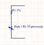
What about this configuration?
I know, it's expensive, but there's no need to have four set of this equivalent resistors. Because you can setup each amplifier's gain equal.
example: R5 value is exactly 20,000 ohms, R6eq coud be set to 1000ohms.
Then: R17 value is 19900, you can set R18eq to 995ohms.
Then both gains Av are: 21
What do you think?
Attachments
The distortion of a BTL circuit is directly proportional to the precision of the resistor network in the circuit. This precision depends directly on the ratio of two different value resistors. It is this ratio that must be made as precise as possible in order to extract maximum performance from your circuit.
In theory this is a no brainer; in practice it is cumbersome.
I have seen commercial applications of BTL circuits that did not use precision resistor networks. They worked, but they introduced a lot of distortion - and sounded terrible at any volume.
Would the gain of each power amp also need to be precisely matched?
Mike
Would the gain of each power amp also need to be precisely matched?
Mike
Yes.
What about this configuration?
I know, it's expensive, but there's no need to have four set of this equivalent resistors. Because you can setup each amplifier's gain equal.
example: R5 value is exactly 20,000 ohms, R6eq coud be set to 1000ohms.
Then: R17 value is 19900, you can set R18eq to 995ohms.
Then both gains Av are: 21
What do you think?
Sure it'll work. It's a precision resistor network inside the DRV134 that makes it work so well. There's also 3 op amps so one chip takes the place of a whole lot of parts. And it's higher precision than you will most likely be able to achieve, although your trimmer circuit with the multi turn pot is a good idea. You could compensate for all the imbalances - including differences in power amplifier gain - with one adjustment.
One consideration is that a multi turn pot might be inductive, introducing an imbalance into the circuit. Resistors with higher inductance are unsuitable for feedback networks. So you'd have a precision, balanced output instrumentation amp with poor AC performance - not the direction you want to head.
The way I see it, the DRV134 does a whole lot of heavy lifting for $6. It adds precision, saves a lot of board space, simplifies the circuit, and probably saves money too.
The key to designing the best circuit for the money, space, and performance, it to have a very clear idea of what you're going to do before you build it. Mistakes can be costly in terms of money and effort - I've scrapped a couple of circuits just this year that I thought I was "almost done with" and went back to the drawing board- so a lot of research and prototype testing (not the same thing as SPICE
") ) is in order.
) is in order. So good luck.
One consideration is that a multi turn pot might be inductive, introducing an imbalance into the circuit. Resistors with higher inductance are unsuitable for feedback networks. So you'd have a precision, balanced output instrumentation amp with poor AC performance - not the direction you want to head.
The way I see it, the DRV134 does a whole lot of heavy lifting for $6. It adds precision, saves a lot of board space, simplifies the circuit, and probably saves money too.
I should give it a try!
Awesome reply!
Thank you very much. I will continue this project and test it to check it out and then I will improve it. I have to buy the heat sinks now.
Thank you very much.
Kind regards.
untill about a decade ago i would never had say, but whatever you need done, its best to look up if there is a chip doing that exactly instead of discrete builds.
This was a big motivation for me to get back into designing audio circuits. When I went to school, we didn't have anything near what's available today. We all had ideas that were impractical because of the devices available. Even transistors and capacitors have been hugely improved since then.
Even the NE5532 is huge compared to what we started with. I built my earliest op amp audio circuits with the CA3140 - talk about a pain you-know-where and expensive too. And something like the LME49600 was Star Trek stuff. It's just so much easier now, with performance only talked about in the classroom a couple of generations ago.

Well, all good advices! Thank you.
Due to my short budget, I'm thinking how to "hack" my PCB, because I've bought 15 of them (that was the minimum), in order to use the DRV134, and I think I got it! So, I could buy a few and use them in this project.
Although I will think about it very good, maybe I should redo my PCB instead. Or: as one friend told me: go on with this current project and improve on the next one
Regards.
Due to my short budget, I'm thinking how to "hack" my PCB, because I've bought 15 of them (that was the minimum), in order to use the DRV134, and I think I got it!
So, I could buy a few and use them in this project.Although I will think about it very good, maybe I should redo my PCB instead. Or: as one friend told me: go on with this current project and improve on the next one
Regards.
I've been down your road, and recently too. I hacked a PC board that I made myself by cutting a whole chunk out and making a replacement piece that could be anchored into place with wires. You put your revised circuit on the replacement piece and solder jumper wires to hook it up. You solder the anchor wires and it's pretty unobtrusive. And, it works.
15 boards? Have you built one? With 15 boards I'd go ahead and build one and see how it works.
15 boards? Have you built one? With 15 boards I'd go ahead and build one and see how it works.
15 boards? Have you built one? With 15 boards I'd go ahead and build one and see how it works.
yup!
That's what I'm going to do
What I've found also is a very good deal for 0.1% resistors
See this link
Is the 1k0 tapping into the correct side of that 14k resistor?While the DRV134 is a great performing chip, I generally follow the concept of "Keep it as simple as possible, but no simpler." In that vein I've gotten good results from this circuit: View attachment 512259
Mike
I've done several commercial designs of bridge amplifiers and resistor ratios were never an issue - 1% is perfectly good. Use a good balanced opamp circuit to split the phases before the power amps, and certain distortions can cancel out leaving you with half or so the inherent PA distortion (even if very low in the first place).
- Status
- This old topic is closed. If you want to reopen this topic, contact a moderator using the "Report Post" button.
- Home
- Amplifiers
- Chip Amps
- A LM1875 BTL approach