Hello all,
I have been experimenting with DC servos with mixed results. Problems are high voltage needed, overshoot/not enough damping, slow response, and not enough correction headroom with normal voltage opamps.
My question is: Can a PID loop be used instead of the regular integrator/LPF that a servo has? I have experience with them in the past but not related to audio.
Thanks,
v
So, I can make an integrator and differentiator with opamps. I can also make an RC low pass filter at something like 1-2 Hz. That is the P. The LPF would feed the I and D.
One would then compare the output of the summed P, I, and D to ground and have an opamp that makes them as close as possible.
I think I'm on the right track but hopefully someone can help with the actual circuit.
Once it is time to tune it the instructions are here https://en.wikipedia.org/wiki/PID_controller
Thanks,
v
You should be able to build up your PID controller from a single op-amp.
http://homepages.wmich.edu/~kamman/ME360PIDImplementation.pdf
Making a PID controller out of an op-amp. - Adventures in Engineering
Ultrastable TEC Controllers for the Coherent 315M-100 DPSS laser head
This will be quite a bit more difficult to "tune" than running three separate stages (one each for P, I and D) and summing their output, which would be the other way to achieve this.
Can you post any information on your current problems with the DC servos? These generally shouldn't be causing the problems, or suffer from the issues, you mention in your first post.
I have been trying this one: http://fullnet.com/~tomg/DC_SERVO.jpg
Attached is the tina file I have been using. I have been using "use initial conditions" and "calculate operating point" for runs and when trying to correct an offset of 250mV there isn't enough voltage headroom in the servo opamp.
With an ideal opamp with infinite voltage the integrator out went up to about 33v in 20 or so seconds and settled there.
I had overshoot/out of control problem once. I think it was when I used ideal opamp with infinite voltage and doubled up on the integrators. I had heard the term "third order servo" and was trying it out.
Hopefully a PID will get it to settle quicker with lower opamp voltage?
Attachments
From the first link,
"To form a PID controller with high frequency gain limit, let the input impedance be generated by a resistor (resistance, ) in series with a resistor (resistance, ) and a capacitor (capacitance ) that are in parallel, and let the feedback impedance be generated by a resistor (resistance, ) and a capacitor (capacitance ) in series."
I have done that in the attached file. The voltage between the PID and LPF is even higher when doing transient with "calculate operating point" but it does eliminate the DC.
And I have run transient out past 600 seconds and it doesn't seem to stabilize(?!) Hopefully there is a simple error here.
Attachments
I've just had a quick look over the initial circuit you have attached in post #5 and think I know where your problems are coming from.
It appears (I would guess) that the designer of the circuit you've linked through to was trying to reduce the output noise from the integrator stage by putting a low pas filter on its output (this is really not necessary). Unfortunately they have used an inverting design where they should have used a non-inverting design so the "DC-Servo" for audio amplifiers that they have designed actually adds in a DC offset to the output of the main OPA541 amplifier stage.
To "fix" your DC servo problems simply remove the low pass filter from the circuit and connect the output of the integrator stage directly to the "FILT_OUT" end of R1.
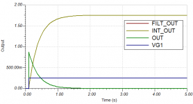
I've attached an updated version of the TINA simulation files that I've tidied up and put this fix in that should show you the circuits response to a shift in the input offset voltage.
I've altered the transient simulation to have a "DC" step change on the input. This makes the servo performance much easier to observe than the previous 60s AC simulations and only takes a fraction of a second to simulate as well.
It appears (I would guess) that the designer of the circuit you've linked through to was trying to reduce the output noise from the integrator stage by putting a low pas filter on its output (this is really not necessary). Unfortunately they have used an inverting design where they should have used a non-inverting design so the "DC-Servo" for audio amplifiers that they have designed actually adds in a DC offset to the output of the main OPA541 amplifier stage.
To "fix" your DC servo problems simply remove the low pass filter from the circuit and connect the output of the integrator stage directly to the "FILT_OUT" end of R1.
I've attached an updated version of the TINA simulation files that I've tidied up and put this fix in that should show you the circuits response to a shift in the input offset voltage.
I've altered the transient simulation to have a "DC" step change on the input. This makes the servo performance much easier to observe than the previous 60s AC simulations and only takes a fraction of a second to simulate as well.
Attachments
Told ya' ")
It's pretty common for the LF cut-off in an amp to destroy the THD at the lower frequencies. That's why I simulate and measure down to 20 Hz. The only fix I've found that strikes a good compromise between settling time and THD is a servo with higher order filtering. I seem to recall Gootee doing that as well, though, I took it a step further by improving on the filter topology as well for the servo in my Modulus-86 amp.
Tom
- Status
- This old topic is closed. If you want to reopen this topic, contact a moderator using the "Report Post" button.
- Home
- Amplifiers
- Chip Amps
- PID servo replacement