I have read that two diode bridges are better then one, and that this can be implemented using a transformer with dual seconderies. Obviously I do not know much about electronics, so I have to ask this basic question. How about using 2 transformers to power a gainclone? Sort of like in a BOSOZ..... One generating the + side and one generating the -. Would this be a better PS then one based on a single transformer? If this is possible and desirable, then how would it be wired? Sort of like in a BOSOZ????? Minus the Zenars? Just trying to complicate my life.....
amo said:I have read that two diode bridges are better then one, and that this can be implemented using a transformer with dual seconderies. Obviously I do not know much about electronics, so I have to ask this basic question. How about using 2 transformers to power a gainclone? Sort of like in a BOSOZ..... One generating the + side and one generating the -. Would this be a better PS then one based on a single transformer? If this is possible and desirable, then how would it be wired? Sort of like in a BOSOZ????? Minus the Zenars? Just trying to complicate my life.....
Yes, you can do that (two transformers), but it's more expensive and it takes more space. As far as performance, it's the same.
Hi,
You mean for a single channel? Well, for two channels, that's probably true.
But I don't think that you'll gain much supply quality from using two transformers for one channel. They are more expensive, bigger in space requirements and different in parameters due to manufacturing tolerances.
OTOH, if you get them for a reasonable price, match them closely for identical output voltage (running both unloaded and under load) out of a bunch of available candidates, and have the mounting space available, then of course it would work.
But for use with a single (channel) gainclone you won't benefit much, as the resulting circuit would be equivalent to one with a single, bigger transformer.
To actually wire two separate transformers:
- wire the primaries of both transformers in parallel, just like wiring a single one, but with the second primary's wires exactly parallel to the first one's,
- use a single common primary fuse for both transformers (as well as a single mains switch), don't give them two dedicated fuses (as this would destroy your chip amp in case one of the fuses blows while the other doesn't),
- keep the transformer secondaries split for now, dedicate a rectifier full bridge (four diodes) to each secondary,
- connect the "-" output of the "upper" bridge to the "+" output of the "lower" bridge and name this signal your "power ground",
- use the "+" output of the "upper" bridge as your signal "V+",
use the "-" output of the "lower" bridge as your signal "V-".
In this scheme I assume that you intend to use transformers with a signle secondary winding (each). With transformers with two secondaries, your freedom to wire them grows "quad-fold", as well as your probability to fry them")
edit:
Hey, Greg was a "little" faster while I was typing...
How about using 2 transformers to power a gainclone?
You mean for a single channel? Well, for two channels, that's probably true.
But I don't think that you'll gain much supply quality from using two transformers for one channel. They are more expensive, bigger in space requirements and different in parameters due to manufacturing tolerances.
OTOH, if you get them for a reasonable price, match them closely for identical output voltage (running both unloaded and under load) out of a bunch of available candidates, and have the mounting space available, then of course it would work.
But for use with a single (channel) gainclone you won't benefit much, as the resulting circuit would be equivalent to one with a single, bigger transformer.
To actually wire two separate transformers:
- wire the primaries of both transformers in parallel, just like wiring a single one, but with the second primary's wires exactly parallel to the first one's,
- use a single common primary fuse for both transformers (as well as a single mains switch), don't give them two dedicated fuses (as this would destroy your chip amp in case one of the fuses blows while the other doesn't),
- keep the transformer secondaries split for now, dedicate a rectifier full bridge (four diodes) to each secondary,
- connect the "-" output of the "upper" bridge to the "+" output of the "lower" bridge and name this signal your "power ground",
- use the "+" output of the "upper" bridge as your signal "V+",
use the "-" output of the "lower" bridge as your signal "V-".
In this scheme I assume that you intend to use transformers with a signle secondary winding (each). With transformers with two secondaries, your freedom to wire them grows "quad-fold", as well as your probability to fry them
edit:
Hey, Greg was a "little" faster while I was typing...
Sounds good to me! I hate that little voice inside my head that keeps telling me that there may be a better, harder way to get it done.... I think I understand now, however, that Mr. Pass used 2 transformers per channel in the BOSOZ because it is a ballanced circuit. Thanks!
Lowering the PS rail voltage?
I am trying to do exactly that as well ... since the transformer I got would only allow me to do a single secondary. HOWEVER, I have another couple of questions
(1) is it possible to make a (V+) - 0 - (V-) (i.e. center tapped) power supply out of single secondary?
(2) if the secondary output voltage is too high, what's an effective way of lowering it?
Thanks!
(1) is it possible to make a (V+) - 0 - (V-) (i.e. center tapped) power supply out of single secondary?
There are a couple of possible ways, but only one really works both safely and efficiently: unwinding the secondary, splitting it, rewinding the two halves in exactly the way the original wire was wound. Try that on a small, cheap transformer first!
Note that you reduce the power handling capability significantly, as now only half of the wire length will have to draw the same amount of current! Altogether, I wouldn't recommend to use a transformer that doesn't fit. I'd suggest you sell the one you have and buy a matching one.
Safety warning here: What I describe is fiddling around with mains components. Rewinding would be safe, but connecting it for a test run should be done with care.
(2) if the secondary output voltage is too high, what's an effective way of lowering it?
That could be done by reducing the winding count of the transformer secondary. But as we already found out, you actually need a new transformer.
sek said:
That could be done by reducing the winding count of the transformer secondary. But as we already found out, you actually need a new transformer.
Thanks for your suggestion =) Certainly I don't wanna fiddle with the transformer windings at the moment
Is it also possible to use a voltage regulator, like the LM338 or LM318? I only need to lower the voltage from 50V DC to around 40V DC ...
Is it also possible to use a voltage regulator, like the LM338 or LM318?
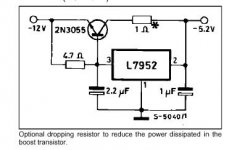
I really don't recommend that, although it would work.I only need to lower the voltage from 50V DC to around 40V DC ...
I think you would be better off with a switching step-down converter due to better efficiency and less heat. Those are cheap (enough) and simple to implement. Now you just need someone to point you on a suitable regulator IC.
Sebastian.
PS: You have only one secondary but want to use the transformer to make a symmetric power supply, nevertheless?
Fishy said:
Thanks for your suggestion =) Certainly I don't wanna fiddle with the transformer windings at the moment
Is it also possible to use a voltage regulator, like the LM338 or LM318? I only need to lower the voltage from 50V DC to around 40V DC ...
LM338 will do fine if you want to get rid of 10V. You really have to use a good heat sink.
For 40W output power over 8Ohm sp. you'll have 2.3A. LM 338 would handle way more (8A max for 10V), so no worry. But again LM338 will dissipate 23W when the speaker's dissipating 40W so, you need a good heat sink and also insolated.
/Greg
Attachments
Wow ... thanks for all those info ...
Well, I will use two separate toroids to power the LM3875. One for +ve, and the other one for -ve. It just happened that the toroids I got have too high a secondary voltage for the LM3875. That's why I am asking all those questions about lowering the voltage and such.
I thought about the LM338 for the positive side of things ... however, I cannot find the -ve counterpart of the regulator that has the same current capabilities (the LM 317 can only do 1.5A)
I will do some research on the switching step-down converter ... hope it would work out fine I really don't want the step down circuit to eat up too much power ...
Well, I will use two separate toroids to power the LM3875. One for +ve, and the other one for -ve. It just happened that the toroids I got have too high a secondary voltage for the LM3875. That's why I am asking all those questions about lowering the voltage and such.
I thought about the LM338 for the positive side of things ... however, I cannot find the -ve counterpart of the regulator that has the same current capabilities (the LM 317 can only do 1.5A)
I will do some research on the switching step-down converter ... hope it would work out fine
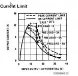
I really don't want the step down circuit to eat up too much power ...The LT1074 is one candidate (inexpensive, easy to implement, capable of delivering up to 5A with sufficient cooling, usable up to 60V, efficient enough): http://www.linear.com/prod/datasheet.html?datasheet=5
Just take care of implementing it properly as surpassing or crosstalking switching noise would ruin your sound quality. At least take care of all the infos in the manufacturer's application note: http://www.linear.com/pub/document.html?pub_type=app&document=47
Hope this helps.
Sebastian.
PS: In case you build it, I beg you to post your progress and results, as many people on the forums are actually waiting for a comparision between chipamps on unregulated vs. regulated supplies!
Thanks!sek said:The LT1074 is one candidate (inexpensive, easy to implement, capable of delivering up to 5A with sufficient cooling, usable up to 60V, efficient enough)
PS: In case you build it, I beg you to post your progress and results
Definitely, I would love to post some pics, progress and results!
I have some DIY speaker project pics online. However I need to organize them a bit ...GregGC said:What about using lm334 and a paralel transistor, like that:
Thanks!
I saw that current boost configuration when I was browsing some 78xx series voltage regulator specs. So, now I have the choice of using a voltage regulator (plus current boost, if needed) or using a switching regulator. Given that Digikey sells inductors (at a low price) for the LMxxxx series of switching regs and efficiency is a concern to me ... I am thinking I'll probably go with the switching reg approach.
Btw ... I am gonna do a tube buffered version of gc ...
Fishy said:
Thanks!
Definitely, I would love to post some pics, progress and results!
Thanks!
I saw that current boost configuration when I was browsing some 78xx series voltage regulator specs. So, now I have the choice of using a voltage regulator (plus current boost, if needed) or using a switching regulator. Given that Digikey sells inductors (at a low price) for the LMxxxx series of switching regs and efficiency is a concern to me ... I am thinking I'll probably go with the switching reg approach.
Btw ... I am gonna do a tube buffered version of gc ...
Tell us how it works when it's rady.
Good luck.
/Greg
- Status
- This old topic is closed. If you want to reopen this topic, contact a moderator using the "Report Post" button.
- Home
- Amplifiers
- Chip Amps
- Dual Transformers for a PS?