For more than a year now I'm lurking in the Diyaudo forums and am highly impressed by the amps some people design and/or build. The more I read the more I wanted to build an amp with my own hands. I have no electronics background but am aware of some basic principles.
Question was what amp to start with. At first I thought well let's take on one of the - let me call them - "evergreen amps". such as the Symasym or Rod Elliots P3A. Then came along a group buy of the PA03 organised by peranders (sjostromaudio.com).
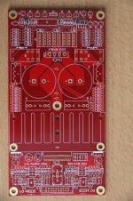
The PA03 is a LM4780 stereo amp designed by a well known Czech developer Pavel Dudek (nickname: Upopa Epops). Peranders offered (and offers) a very high quality pcb for this amp. The board is a kind of all in one solution as the power supply is included on the board and all you have to do is populate the board. Connect a transformer, hook up your audio gear and off you go.
Well that's the theory. But I soon discovered that there is more to it than that. But my mind was set, my first amp had to be the PA03. For technical details about the amp I refer to the website mentioned before.
In several posts I like to show the progress in this build, I think it will take a few weeks to complete the amp. As a newb I like to learn from comments on the build and perhaps get an answer from more experienced readers when I'm stuck. At the same time I hope to be able to show other starters that is is possible to build your own amp.(At least that's the idea !!!!!). Another reason to show my build here is a post in the Group Buys section by Upopa Epops, the designer of the PA03 in which he complained about the lack of response from builders of his design.
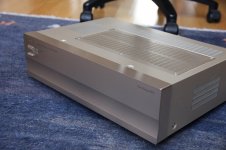
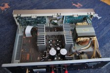
Okay So I joined the group buy and a few weeks later a beautifully designed board dropped on the doormat. Ok what now, First I needed a case for my build. Then I saw the case build by philbool (See the post "My first gainclone"). Wow what a beauty is that. As I have no access to CNC tools and a custom build would be too expensive I decided to look for a second hand amp case. I checked the local thrift shops and websites for second hand electronics. And then I bought this old Pioneer M10X power amp. It seemed suitable for my purpose. But now what ??? As a genuine newb I have no tools at all, no DMM no soldering iron, no nothing !!!!! Mmmmmmm, time to think about it.
To be continued ......
In the pictures the new home for the PA03 and the PA03 board.
Question was what amp to start with. At first I thought well let's take on one of the - let me call them - "evergreen amps". such as the Symasym or Rod Elliots P3A. Then came along a group buy of the PA03 organised by peranders (sjostromaudio.com).
The PA03 is a LM4780 stereo amp designed by a well known Czech developer Pavel Dudek (nickname: Upopa Epops). Peranders offered (and offers) a very high quality pcb for this amp. The board is a kind of all in one solution as the power supply is included on the board and all you have to do is populate the board. Connect a transformer, hook up your audio gear and off you go.
Well that's the theory. But I soon discovered that there is more to it than that. But my mind was set, my first amp had to be the PA03. For technical details about the amp I refer to the website mentioned before.
In several posts I like to show the progress in this build, I think it will take a few weeks to complete the amp. As a newb I like to learn from comments on the build and perhaps get an answer from more experienced readers when I'm stuck. At the same time I hope to be able to show other starters that is is possible to build your own amp.(At least that's the idea !!!!!). Another reason to show my build here is a post in the Group Buys section by Upopa Epops, the designer of the PA03 in which he complained about the lack of response from builders of his design.
Okay So I joined the group buy and a few weeks later a beautifully designed board dropped on the doormat. Ok what now, First I needed a case for my build. Then I saw the case build by philbool (See the post "My first gainclone"). Wow what a beauty is that. As I have no access to CNC tools and a custom build would be too expensive I decided to look for a second hand amp case. I checked the local thrift shops and websites for second hand electronics. And then I bought this old Pioneer M10X power amp. It seemed suitable for my purpose. But now what ??? As a genuine newb I have no tools at all, no DMM no soldering iron, no nothing !!!!! Mmmmmmm, time to think about it.
To be continued ......
In the pictures the new home for the PA03 and the PA03 board.
Attachments

Episode 2
For you experts it's a no-brainer. Buy the parts, heat up the soldering iron. Put the parts in place, connect the power to the wall outlet and .....the PA03 is making music. Just a straightforward build. But for me it's all unknown territory. Okay, I've got the pcb and a case, now what.
First: I've got no electronics toolkit;
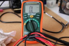
A digital multimeter seems to be a necessity. Experts told me Fluke is the way to go. They are accurate and will last a lifetime. But for me way too expensive. Then I saw on Youtube EEVblog #91 on which Dave Jones gave an interesting kind of lecture on multi-meters. He made a recommendation of the Extech EX330. So I bought it.
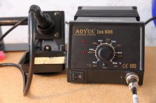
For soldering it seemed useful to have some sort of station with temperature control. The pros tell me Weller is the brand to have. But again for me way too expensive. On a Dutch site I've read some very positive reviews about the AOYUE 936. This is a 35 watt soldering station with precise temperature control.(more about that later !!!) It is reasonably priced so it went into the shopping basket together with a chisel soldering tip.
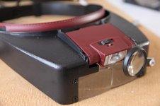
The parts on the pcb are very close to each other and it is easy to create unwanted solder bridges so I needed some magnifying loupe. For this I bought the Velleman VTMG13 headband loupe with integrated led light. Magnifying factor 0.375x - 0.75x - 2.125x - 2.5x.
For just 15 euros a very nice and handy product with a reasonable build quality.
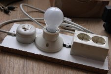
In reaction to my post AndrewT advised to build a Mains Bulb Tester. Google is your friend and on Dim Bulb Tester for your amps and other electrical equipment • www.cab1net.com I found the answer.
To be continued ......
In the pictures the Aoyue, dmm, Mains Bulb Tester and Velleman magnifier
For you experts it's a no-brainer. Buy the parts, heat up the soldering iron. Put the parts in place, connect the power to the wall outlet and .....the PA03 is making music. Just a straightforward build. But for me it's all unknown territory. Okay, I've got the pcb and a case, now what.
First: I've got no electronics toolkit;
A digital multimeter seems to be a necessity. Experts told me Fluke is the way to go. They are accurate and will last a lifetime. But for me way too expensive. Then I saw on Youtube EEVblog #91 on which Dave Jones gave an interesting kind of lecture on multi-meters. He made a recommendation of the Extech EX330. So I bought it.
For soldering it seemed useful to have some sort of station with temperature control. The pros tell me Weller is the brand to have. But again for me way too expensive. On a Dutch site I've read some very positive reviews about the AOYUE 936. This is a 35 watt soldering station with precise temperature control.(more about that later !!!) It is reasonably priced so it went into the shopping basket together with a chisel soldering tip.
The parts on the pcb are very close to each other and it is easy to create unwanted solder bridges so I needed some magnifying loupe. For this I bought the Velleman VTMG13 headband loupe with integrated led light. Magnifying factor 0.375x - 0.75x - 2.125x - 2.5x.
For just 15 euros a very nice and handy product with a reasonable build quality.
In reaction to my post AndrewT advised to build a Mains Bulb Tester. Google is your friend and on Dim Bulb Tester for your amps and other electrical equipment • www.cab1net.com I found the answer.
Thanks a lot AndrewT I think this is just what I need. In the PA03 build guide Pavel advised to gradually increase the voltage for first startup. I think Pavel Dudek meant to use a variac which I don't have. I hope the Bulb Tester will do instead. Yesterday I had some spare time and I built one.Old equipment as well as newly built ones can be tested with the Dim Bulb Tester. It can save you a lot of headaches from sparks or blowing up fuses and parts because once there is a short, the Dim Bulb Tester will absorb the current and light up brightly. If all is well, it will lit up dimly and you can actually power up your equipment while plugged into this tester.
To be continued ......
In the pictures the Aoyue, dmm, Mains Bulb Tester and Velleman magnifier
Attachments
Episode 3
Okay A case is bought, soldering iron is warming up. Time to order the parts. Peranders offers a PA03 Bill Of Materials (BOM) for three suppliers, Elfa Distrelec, Mouser and Farnell. Mouser is the most to my liking. It has a huge collection of parts, a nice website. It's easy to get access to data sheets and what's more most components can be ordered in small quantities.
Mouser has BOM import tool. After some fiddling it is rather easy to import the provided BOM. Tip: It will not import unless you remove column G (Note). After import Mouser shows a long list with part numbers found, but also with several Parts Not Resolved. For instance Mouser part number 511-4020 described as “14-stage ripple carry binary counter” was designated “Obsolete”. Now for a newbee like me searching for compatible parts is a daunting task,. Happily Mouser makes suggestions for alternatives. Mmmmm, worry , worry. In this case I ordered part number 595-CD4020BE “TI Counter ICs 14-Bit Ripple-Carry”.
Right or wrong: Perhaps someone can help me out here ??
For future builders it's useful to know there is a small typo in the build guide. On page 3/9 chapter “Power Amplifier” Pavel mentions the value of capacitor C14. He has acknowledged that it is in fact C15 he is talking about. So for a normal stereo box the value of C15 (and not C14) has to be 47uF. AFAIK BOM and schematic are correct.
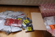
After a short while Mouser delivered my order. Nicely packed with a lot of small bags each labeled with information about the contents of the bag. Sensitive components packed in anti static bags. For all the experts here this is nothing new, but remember newbee here!!
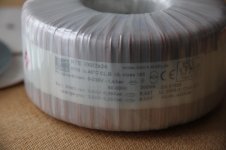
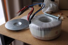
The transformer I have chosen is a toroidal German Block 2X24V 300VA. Perhaps more power than needed for this amp. But when I get the hang of building an amp perhaps there are other designs to try. BTW didn't know a transformer like this is so bulky and heavy.
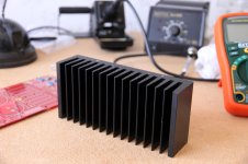
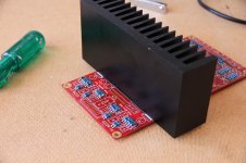
Pavel Dudek advises a Pada heatsink of 100x100 mm with 40 mm ribs and thermal resistance of 1,60 C/W. Unfortunately this sink will not fit in my case so I had to look for an alternative. I have chosen a Fischer heat sink type SK 85 75 SA. It measures 160x75 mm with 40 mm ribs. It is black anodized and has a 10 mm baseplate. According to Fischer the thermal resistance is between 1.35 – 0.6 K/W. I think the effectiveness of the heat sink will also depend on the way I mount the LM4780. Again a lot of things to ponder.
In the pictures, parts unboxed, transformer and Fischer heatsink
To be continued ......
Okay A case is bought, soldering iron is warming up. Time to order the parts. Peranders offers a PA03 Bill Of Materials (BOM) for three suppliers, Elfa Distrelec, Mouser and Farnell. Mouser is the most to my liking. It has a huge collection of parts, a nice website. It's easy to get access to data sheets and what's more most components can be ordered in small quantities.
Mouser has BOM import tool. After some fiddling it is rather easy to import the provided BOM. Tip: It will not import unless you remove column G (Note). After import Mouser shows a long list with part numbers found, but also with several Parts Not Resolved. For instance Mouser part number 511-4020 described as “14-stage ripple carry binary counter” was designated “Obsolete”. Now for a newbee like me searching for compatible parts is a daunting task,. Happily Mouser makes suggestions for alternatives. Mmmmm, worry , worry. In this case I ordered part number 595-CD4020BE “TI Counter ICs 14-Bit Ripple-Carry”.
Right or wrong: Perhaps someone can help me out here ??
For future builders it's useful to know there is a small typo in the build guide. On page 3/9 chapter “Power Amplifier” Pavel mentions the value of capacitor C14. He has acknowledged that it is in fact C15 he is talking about. So for a normal stereo box the value of C15 (and not C14) has to be 47uF. AFAIK BOM and schematic are correct.
After a short while Mouser delivered my order. Nicely packed with a lot of small bags each labeled with information about the contents of the bag. Sensitive components packed in anti static bags. For all the experts here this is nothing new, but remember newbee here!!
The transformer I have chosen is a toroidal German Block 2X24V 300VA. Perhaps more power than needed for this amp. But when I get the hang of building an amp perhaps there are other designs to try. BTW didn't know a transformer like this is so bulky and heavy.
Pavel Dudek advises a Pada heatsink of 100x100 mm with 40 mm ribs and thermal resistance of 1,60 C/W. Unfortunately this sink will not fit in my case so I had to look for an alternative. I have chosen a Fischer heat sink type SK 85 75 SA. It measures 160x75 mm with 40 mm ribs. It is black anodized and has a 10 mm baseplate. According to Fischer the thermal resistance is between 1.35 – 0.6 K/W. I think the effectiveness of the heat sink will also depend on the way I mount the LM4780. Again a lot of things to ponder.
In the pictures, parts unboxed, transformer and Fischer heatsink
To be continued ......
Attachments
@Rol
Rol, would you be so kind to give me some hints here ??The only issue I got was setting the correct jumpers
help on transformer wiring ??
Yesterday I was searching the forums for information about LM4780 amps when I stumbled upon a post by member Redjr
http://www.diyaudio.com/forums/chip-amps/277081-pa03-startup-mistake.html
So I thought better be careful here. I checked the PA03 schematic in combination with my 2x24V transformer on how to wire. Attached are pictures of my transformer and the connectors on the board. As newbee it looks so simple to connect:
- red wire to point 3;
- black wire to point 4;
- grey wire to point 5;
- orange wire to point 6
But isn't that a short in 3 and 6 ??
or do I have to connect the center taps different ?
- grey wire to point 3
- orange wire to point 4
- red wire to point 5
- black wire to point 6
Dear experts please help me out here ?
To be continued ......
Yesterday I was searching the forums for information about LM4780 amps when I stumbled upon a post by member Redjr
I made a stupid mistake tonight while trying to start my new PA03 LM4780 chip amp. I now need to know what has been cooked! I made a big error hooking up the secondary from the tranny to the PCB. I mistakenly assumed the center tap were the two inner most connectors, but they weren't. The PCB layout seems a little odd with the center-tap being the two outside connectors instead of the common ground in the middle were the two secondary windings are connected together. Live and learn.
http://www.diyaudio.com/forums/chip-amps/277081-pa03-startup-mistake.html
So I thought better be careful here. I checked the PA03 schematic in combination with my 2x24V transformer on how to wire. Attached are pictures of my transformer and the connectors on the board. As newbee it looks so simple to connect:
- red wire to point 3;
- black wire to point 4;
- grey wire to point 5;
- orange wire to point 6
But isn't that a short in 3 and 6 ??
or do I have to connect the center taps different ?
- grey wire to point 3
- orange wire to point 4
- red wire to point 5
- black wire to point 6
Dear experts please help me out here ?
To be continued ......
Attachments
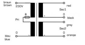
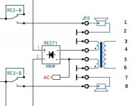
That is a terrible way to show the wiring of the transformer secondaries to the rectifier and smoothing capacitors.
They are misusing the ground symbol and showing everything connected to some general "ground".
That is NOT the way one builds a Centre Tapped transformer into a dual polarity PSU.
The Centre tap must connect to the centre point junction between the two smoothing capacitors. CT DOES NOT go to ground.
Get some better PSU tutorials. Start with ESP and TNT.
Episode 4
New multimeter, new soldering station time to start occupying the PA03 board. As I have little or no soldering experience I decided first to play a little with the temperature control on my Aoyue. The Stannol solder I use has a melting temperature of about 190 C so I set temperature to 200 C. When I tried to melt some solder on the tip of my iron the solder didn't melt at all. Set at 250 C just melted the solder. So I guess calibration of the Aoyue is way off. That renders the temperature scale pretty much useless and I had to develop some feeling for the right temperature setting.
During soldering the parts should lie on a semi hard pad (rubber or felt liner) says Pavel. I had nothing of the kind at hand so I did without, but I guess such a soft pad is a big plus as it is stops movement of the components while soldering. The components are neatly arranged on the board but (for a newb) very close together. Meaning there is a risk of creating solder bridges. In this regard the Velleman magnifying glasses were extremely useful. Pavel is using quite a lot of (parallel) resistors on the board. At the benefit of better reliability, more accuracy and lower thermal distortion. This explains the relatively large number of components on the board.
For me the build got tricky when I had to attach the heat sink to the board. The correct placement of the heat sink is important. A big help is that a profile of the sink is outlined on the board. If the base of the sink accurately follows the line on the board the 27 pins of the LM4780 are almost sliding into its mounting holes. And I tell you the pins are really tiny and you don't want to fiddle with them too much. The back of my LM4780 is not insulated so I had to choose to insulate or not. I choose not to in favor of a better heat transfer. As the LM4780 cooling surface is connected to the negative power supply you have to be careful when mounting the board in a case. When the two voltage regulators are also attached to the heat sink they have to be insulated.
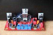
I am a little bit of a control freak and a newb so I put a lot of thought in the way to attach the LM4780 to the sink. The standard way to mount the chip is with mounting screws. However I was afraid that a small mistake in drilling would give me a lot of problems getting the chip in place. Therefore I chose the spring clip from Fischer Elektronik (THFM 1) and this is really a recommendation. Very easy to fasten the chip.
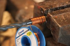
The two inductors on the board were wound by myself. For the parameters I used the Air Cored Inductor Calculator. Air Cored Inductor Calculator | M0UKD – Amateur Radio Blog About twenty turns of 1 mm enameled wire on an 8 mm drill. Don't forget to scrape of the enamel from both endpoints before soldering.
For me populating the board was really fun. When possible I measured every component before inserting it into the board.
in the pictures: Correct placement of the heat sink, Winding the inductor, spring clip on the LM4780
To be continued ......
New multimeter, new soldering station time to start occupying the PA03 board. As I have little or no soldering experience I decided first to play a little with the temperature control on my Aoyue. The Stannol solder I use has a melting temperature of about 190 C so I set temperature to 200 C. When I tried to melt some solder on the tip of my iron the solder didn't melt at all. Set at 250 C just melted the solder. So I guess calibration of the Aoyue is way off. That renders the temperature scale pretty much useless and I had to develop some feeling for the right temperature setting.
During soldering the parts should lie on a semi hard pad (rubber or felt liner) says Pavel. I had nothing of the kind at hand so I did without, but I guess such a soft pad is a big plus as it is stops movement of the components while soldering. The components are neatly arranged on the board but (for a newb) very close together. Meaning there is a risk of creating solder bridges. In this regard the Velleman magnifying glasses were extremely useful. Pavel is using quite a lot of (parallel) resistors on the board. At the benefit of better reliability, more accuracy and lower thermal distortion. This explains the relatively large number of components on the board.
For me the build got tricky when I had to attach the heat sink to the board. The correct placement of the heat sink is important. A big help is that a profile of the sink is outlined on the board. If the base of the sink accurately follows the line on the board the 27 pins of the LM4780 are almost sliding into its mounting holes. And I tell you the pins are really tiny and you don't want to fiddle with them too much. The back of my LM4780 is not insulated so I had to choose to insulate or not. I choose not to in favor of a better heat transfer. As the LM4780 cooling surface is connected to the negative power supply you have to be careful when mounting the board in a case. When the two voltage regulators are also attached to the heat sink they have to be insulated.
I am a little bit of a control freak and a newb so I put a lot of thought in the way to attach the LM4780 to the sink. The standard way to mount the chip is with mounting screws. However I was afraid that a small mistake in drilling would give me a lot of problems getting the chip in place. Therefore I chose the spring clip from Fischer Elektronik (THFM 1) and this is really a recommendation. Very easy to fasten the chip.
The two inductors on the board were wound by myself. For the parameters I used the Air Cored Inductor Calculator. Air Cored Inductor Calculator | M0UKD – Amateur Radio Blog About twenty turns of 1 mm enameled wire on an 8 mm drill. Don't forget to scrape of the enamel from both endpoints before soldering.
For me populating the board was really fun. When possible I measured every component before inserting it into the board.
in the pictures: Correct placement of the heat sink, Winding the inductor, spring clip on the LM4780
To be continued ......
Attachments
You can check the calibration of your soldering iron.
Make up a tiny ring of thin solder that fits around the tip. This could be around 1 to 1.5mm diameter and would use just 3 to 4 mm of 22g or 24g solder.
Place the solder around the tip and set to 180° C.
gradually increase the temperature until the solder melts.
Now add ~100C to that temperature.
That is probably a good tip temp for general soldering.
You may get away with +90C, or for big component jobs +150C
But 274°C will probably be too slow and speed determines how much heat passes to the inside of the component.
At a right temperature you may find that a 2 to 3 second application of tip to job completes the soldering.
Buy eutectic for electric soldering.
the 63/37 melts at 184°C and +100C gives a tip temp of 284°C
There are some triple eutectics and one quad eutectic .
Last edited:
ooooh nice. I like it, i like it, i like it a lot ") . I was in the same GB.
. I was in the same GB.
Still don't have the guts to start the build. Sold it to myself as a nice winter project for my son and I.
Guess what happens now.....it is getting winterish. So I am running out of excuses.
Now I am getting "forced" to start! But first I need all the components. Some tips there?
Many thanks for this great insight. Keep it coming.
. I was in the same GB. Still don't have the guts to start the build. Sold it to myself as a nice winter project for my son and I.
Guess what happens now.....it is getting winterish. So I am running out of excuses.
Now I am getting "forced" to start! But first I need all the components. Some tips there?
Many thanks for this great insight. Keep it coming.
That is probably a good tip temp for general soldering.
You may get away with +90C, or for big component jobs +150C
But 274°C will probably be too slow and speed determines how much heat passes to the inside of the component.
At a right temperature you may find that a 2 to 3 second application of tip to job completes the soldering.
You've just reminded me of an occasion in a previous job when I nearly came to blows with the Quality Control Offier because he kept turning my iron down to 280 behind my back when i left the workshop. The little **** was obsessed everyone had to keep their irons displaying at 280 for QC reasons. It want's to be in that region but the gauge is never that accurate. If your too cold you'll just end up with a dry-joint or lifting a track or messing up the through-plating. Common leaded components should be two or three seconds tops to solder each leg. Ideally the solder bridge between the the pad and the leg should be slightly concave. Its not essential but if its concave you can be fairly sure its a good connection.
Sent from my SM-G920F using Tapatalk
- Home
- Amplifiers
- Chip Amps
- Newbee build: PA03 amp (LM4780)