The LME49710 and LME49720 have very low input current and make good line level preamps, but I would like to use a DC servo to automatically zero it. My amplifier is DC coupled, so it seems like a good idea to keep this residual offset as low as possible.
I am uncertain how to incorporate a DC servo onto the opamp having a gain of 3x. Help is much appreciated Diyers!
I am uncertain how to incorporate a DC servo onto the opamp having a gain of 3x. Help is much appreciated Diyers!
If you keep the feedback impedances reasonably low (a few kΩ or below) you should have no issues with DC offset. The offset of the LME49710 is 50 uV typical, 700 uV max. You'll be hard pressed to design a DC servo that'll improve on the 50 uV. In fact, the servo is more likely to make matters worse due to its own offset voltage.
If you really want to go the DC servo route, I suggest playing with it in the simulator first to get an idea of what the offset voltage will be with/without servo. You may find some inspiration in Figure 28 of the LME49600 data sheet as it shows the implementation of a servo around an op-amp circuit. Just take out the LME49600 part of the circuit. Note that you'll want to use something other than the LME49710 for the servo, though. I suggest looking at CMOS input parts to get the input bias current down in the pA range or fA if you can.
Tom

Thank you for your response, Tom. The servo circuit in the 49600 opamp headphone driver is helpful and illustrates its application very well.
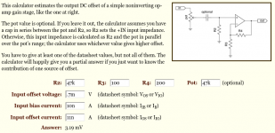
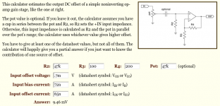
I was using an offset calculator with the typical and maximum values supplied in the 49720 data sheet. Based on the typical values, offset was a bit under 4mV, and just under 10mV with the higher max values. I thought these were rather high. Maybe I made an error or this calculator provided an incorrect answer? Electronics Calculators
I was using an offset calculator with the typical and maximum values supplied in the 49720 data sheet. Based on the typical values, offset was a bit under 4mV, and just under 10mV with the higher max values. I thought these were rather high. Maybe I made an error or this calculator provided an incorrect answer? Electronics Calculators
Attachments
if you use a DC coupled amplifier, then I always suggest you have some form of DC detection............. My amplifier is DC coupled, so it seems like a good idea to keep this residual offset as low as possible. ................
That detection then operates what YOU decide is necessary to prevent damage.
Both pics show R2=47k and R3=100r and R4=200r, R3||R4=66r7Thank you for your response, Tom. The servo circuit in the 49600 opamp headphone driver is helpful and illustrates its application very well.
I was using an offset calculator with the typical and maximum values supplied in the 49720 data sheet. Based on the typical values, offset was a bit under 4mV, and just under 10mV with the higher max values. I thought these were rather high. Maybe I made an error or this calculator provided an incorrect answer? Electronics Calculators
This maximises output offset.
For a DC coupled pre (or any amplifier that is DC coupled) I would expect the designer to minimise output offset.
Last edited:
Hi Andrew, without a circuit diagram I'm not entirely clear on what you mean by DC detection - do you mean a circuit that opens continuity of the output if the offset becomes higher than a predetermined safe voltage, like a protection circuit?
Those values in the images were based on suggestions I found online for 3x gain. I haven't found any clear answers to what should be ideal for low offset with gain. That's what led to this thread. The most common suggestion is low feedback resistor values. Douglas Self used 2k2 and 1k during his testing of the LM4562 at 3.2x gain. He never mentioned his output offset during testing but his values give the same high offset results in the calc. (According to TI product managers, the LM4562 is the same die as the LME49720 so results should be interchangeable)
I'm looking for a way to minimize offset current differences or the effects. If a DC servo isn't a good way to correct DC offset in a line level gain circuit, how does one minimize the offset directly? What values or additional circuitry correct any offset?
Thank you for your replies.
Last edited:
An opamp, or an amplifier, that uses differential input requires that the INPUTs to the circuit match for voltages and currents.
This requires that the INPUTS require to see the same resistance.
Your +ve input sees 47k plus some parasitics.
Your -ve input sees 66r7 plus some parasitics.
This is because you have a mixed AC & DC coupled amplifier.
Change the circuit to AC coupled and your problem of unmatched input resistances can easily be solved.
or
Change the circuit to DC coupled (at both inputs) and your problem of unmatched input resistances can be solved, but then you run the increased risk of system damage.
A side effect of unmatched input resistances is an increase in drift of the output offset.
Not only does mixed AC & DC coupling increase the output offset, it also increases how much that offset changes, particularly during warm up and/or from season to season.
Last edited:
Rather than using an on-line tool, I suggest looking at Walt Jung's "Op Amp Applications Handbook", Section 1-4. The book can be downloaded for free. See link on the Reference Texts section of my website. Franco, Chapter 5 is a good resource on this topic as well.
You'll gain far more understanding from reading a couple of pages in these references than from using an on-line tool. It's a little bit more work to gain the knowledge, but it pays dividends later.
Tom
You'll gain far more understanding from reading a couple of pages in these references than from using an on-line tool. It's a little bit more work to gain the knowledge, but it pays dividends later.
Tom
- Status
- This old topic is closed. If you want to reopen this topic, contact a moderator using the "Report Post" button.
- Home
- Amplifiers
- Chip Amps
- LME49720 DC Servo question