Hello everyone,
First of all I have to apologize a bit for this very beginner question. I tried to search and google around for a couple of evenings, but I'm none the wiser...
I'm putting together my first ever diy-amp, the Chipamp 3886 stereo kit to be exact. I don't know anything about electronics as I normally make diy-speakers just for the woodworking, but decided to give this side of things a go...
Anyway, this is my problem:
I have a toroidal transformer with the following markings:
25-0-25 V
Blue - black - blue
The primary wires are red, that's no problem and then out come the two blue ones and a black one.
Am I correct that my transformer has single secondaries?
From the kit manual I understood that I should use a trafo with dual secondaries. Can I use the trafo I have and if so how do I connect it?
Many thanks in advance and sorry if this has been asked and answered before. I couldn't find anything that was clear enough for me..
Your transformer is fine. Its the equivalent of two 25 volts windings in series with a common centre tapping. So its fine for the chip amp. If you needed an application with two isolated 25 volts windings then it would not be suitable... but you don't
So the black wire is the 'ground' and the two blue connect to the bridge (either way around, it doesn't matter)
(when you power your amp up for the first time, use a bulb tester... it can save expensive mistakes)
So the black wire is the 'ground' and the two blue connect to the bridge (either way around, it doesn't matter)
(when you power your amp up for the first time, use a bulb tester... it can save expensive mistakes)
Your transformer is fine. Its the equivalent of two 25 volts windings in series with a common centre tapping. So its fine for the chip amp. If you needed an application with two isolated 25 volts windings then it would not be suitable... but you don't
So the black wire is the 'ground' and the two blue connect to the bridge (either way around, it doesn't matter)
(when you power your amp up for the first time, use a bulb tester... it can save expensive mistakes)
Ok thanks!
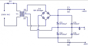
I want to clarify a bit more..
The Chipamp.com PSU board has places for four secondary wires and the schematic in the manual also has four leads coming from the trafo.
This is from the manual:
An externally hosted image should be here but it was not working when we last tested it.
And also on this picture from the chipamp.com pages I can see four wires going in to the PSU:
An externally hosted image should be here but it was not working when we last tested it.
Do I have to split the two blue ones in to four perhaps?
Oh and yeah the bulb tester is the next thing to put together while I wait for the last parts to arrive for the amp.
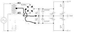
Like this.
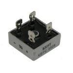
You can use one of these, cheap, bullet-proof, get one that is way over-rated....if you want, bolt it up to a small plate of Aluminium.
----------------------------------------------------------Rick..........
Attachments
Last edited:
Like this.
Alright, thanks again that looks clear enough I think.
I'll have to take a look at the pcb when I come home from work, but I guess I have to modify it a bit? Or I mean I have to solder wires somewhere.
You only have the description to go off when buying, along with any manufacturer markings that allow you to look up any data sheets.
The PCB should be easy to rework by removing a bridge. You will have to cut a trace on the bridge that is remaining to isolate it from ground. Use a modelling knive to cut the print twice a few mm apart and lift the print away to get good isolation. Add a link from bridge to tranny and join the two 'grounds' and you should be fine.
The PCB should be easy to rework by removing a bridge. You will have to cut a trace on the bridge that is remaining to isolate it from ground. Use a modelling knive to cut the print twice a few mm apart and lift the print away to get good isolation. Add a link from bridge to tranny and join the two 'grounds' and you should be fine.
One can convert a dual secondary transformer to a centre tapped transformer.
One cannot convert a centre tapped transformer to a dual secondary transformer. Unless you rewind the secondary. A difficult and time consuming job.
Since both types of transformer can become the centre tapped type, then the single bridge rectifier PSU shown in posts 4&5 can be used.
The dual secondary/dual rectifier/dual DC output style can ONLY be used with a dual secondary transformer.
With care one can convert the dual rectifier PCB to a single rectifier style. But one needs to work out the routes of the traces and work out which 4 diodes to delete and which trace to cut/join.
Pics (both sides) of your PCB will identify what you have and whether it needs to be converted.
Uh huh... Things might be getting a little out of my league. Maybe it's the easiest if I just buy a new trafo.
I hope it's OK to post ebay links here?
Would this be the transformer I need? Avel Y236652 250VA 25V 25V Toroidal Transformer 122 625 | eBay
I believe that this is the datasheet: http://www.avellindberg.com/pdf/avel_y23_range.pdf
There it says that it can be wired for 230 V input and I believe that it has dual secondaries?
Its a shame to buy a new transformer just because of this but yes, the ebay picture is of one with dual secondary's. Its really is only a few minutes work to make the board suitable for your tranny. And if using a bulb tester then you can test just the power supply and be sure its good.
This a wee bit cheaper,
It like the Avel is 'Fabrique En Chine'.
Possibly even from the same factory
Shipping is Very fast. AS-3225 - 300VA 25V Transformer - AnTek Products Corp
It like the Avel is 'Fabrique En Chine'
.Possibly even from the same factory
Shipping is Very fast. AS-3225 - 300VA 25V Transformer - AnTek Products Corp
Its a shame to buy a new transformer just because of this but yes, the ebay picture is of one with dual secondary's. Its really is only a few minutes work to make the board suitable for your tranny. And if using a bulb tester then you can test just the power supply and be sure its good.
I know, but for this first build maybe I make things a bit easier. I have another amp in mind for my daughter so I can use the trafo there and be more adventurous.
Thank you a lot for your help. Really appreciated!
And everyone else of course also! Thanks!
post a pic of top and bottom side of your PSU PCB.........................
Pics (both sides) of your PCB will identify what you have and whether it needs to be converted.
It will match your existing transformer or it can be altered to match your existing transformer.
The Mains Bulb Tester will protect your equipment from damage, no matter how wrong you get the wiring. It even protects the mains Fuse from damage !
Ok thanks!
I want to clarify a bit more..
The Chipamp.com PSU board has places for four secondary wires and the schematic in the manual also has four leads coming from the trafo.
This is from the manual:
An externally hosted image should be here but it was not working when we last tested it.
And also on this picture from the chipamp.com pages I can see four wires going in to the PSU:
An externally hosted image should be here but it was not working when we last tested it.
Do I have to split the two blue ones in to four perhaps?
Oh and yeah the bulb tester is the next thing to put together while I wait for the last parts to arrive for the amp.
What is the purpose of the two 2.2K resistors
After the diode bridge
- Status
- This old topic is closed. If you want to reopen this topic, contact a moderator using the "Report Post" button.
- Home
- Amplifiers
- Chip Amps
- Another noob transformer question