Hello, I'm new to this forum so I'm sorry if this is the wrong place for my question.
I'm building a simple headphone amp/mixer that will mix a guitar signal with a stereo aux in and send both out to headphones. I'm using a 9V battery for my prototypes, but eventually I want it to share the 9V wall-wart that my effects pedals use.
I'd also like to use a TRS jack with the power ground connected through the ring, so that the 1/4" mono guitar input acts as a power switch. That way, I can leave this device permanently on my pedal board, but this device would not use power if I'm not using it.
I've read some about having the grounds connect to the chassis at a single point to minimize noise, so I'm planning on only grounding the PCB circuit to a volume pot and into the chassis. All of the I/O jacks' grounding will just be to the chassis and not directly connected to the PCB. Also the circuit is all analog.
Would there be any problems with this method? Please let me know if you need more details about my circuit.
Thanks!
Attachments
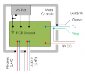
Your PCB ground to chassis connection is relying on the pot body. I think you are better off putting a wire from the PCB to a tag on the chassis, and forget grounding the pot with that link.
Try it, you might have some hum or noise issues. If you do then you can use isolated sockets for i/o and ground them at the PCB.
Try it, you might have some hum or noise issues. If you do then you can use isolated sockets for i/o and ground them at the PCB.
I don't understand the 9V DC
It looks to me that the Guitar signal is returned from the R of TRS through the 9V and then comes back to the PCB.
The T & R may be a balanced signal (S is correctly connected to Chassis) and need to be processed as a balanced impedance signal.
That's just the standard method to switch power in effects pedals on and off. It works by using a standard 1/4" TS "mono" plug to short the ring to the sleeve in a TRS jack, thereby connecting the battery to ground. It's normally the output jack on the pedal and is usually labeled "Out/Power."
Mike
Yes sorry if that wasn't clear. Only the jack is TRS, but the signal in is unbalanced an will use a TS plug.
Your PCB ground to chassis connection is relying on the pot body. I think you are better off putting a wire from the PCB to a tag on the chassis, and forget grounding the pot with that link.
Try it, you might have some hum or noise issues. If you do then you can use isolated sockets for i/o and ground them at the PCB.
Is the connection of the pot body to the chassis not reliable? Would using one of the jack sleeves (say the headphone jack) to the PCB ground be better? I haven't gotten all of my hardware yet, but I don't think the chassis will have lugs in it, so I guess I could mount one myself if it's necessary.
- Status
- This old topic is closed. If you want to reopen this topic, contact a moderator using the "Report Post" button.