I know this subject has been on many previous threads but I am trying to find out how to calculate the input and output impedance of an attenuator based on a simple type potentiometer, pi type and a pi type with a series resistor at the inlet to the pi network. Its the theory I am after.
These resistor layouts appear on various switched type attenuators.
I think I understand how to work out the input impedance but not completely sure. I am looking at using a switched type attenuator using two 2 pole switches 6 way with pcb mount terminations to give course and fine volume control.
These resistor layouts appear on various switched type attenuators.
I think I understand how to work out the input impedance but not completely sure. I am looking at using a switched type attenuator using two 2 pole switches 6 way with pcb mount terminations to give course and fine volume control.
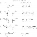
for pi attenuator I add the series resistor with the second resistor to ground and then take parallel sum, ie for r1 (series), r2 first resistor to gnd, r3 2nd resistor to gnd,
input imp = r2 || (r1+r3).
for potentiometer I take input impedance as r1 section of pot where total r = r1 + r2.
input imp = r2 || (r1+r3).
for potentiometer I take input impedance as r1 section of pot where total r = r1 + r2.
Just to clarify what you are saying; is it that the load impedance will be much greater than Rin meaning Rin can be neglected.
I can understand the theory for Rout from your formula except for 5, why does R2 have no effect.
Hi,
Rload can be neglected assuming its very high, it usually isn't.
Assuming Rsource is very low, an ideal voltage source is safer.
For 5 Rout = R1 + R2||Rsource and if Rsource is zero ....
rgds, sreten.
Last edited:
- Status
- This old topic is closed. If you want to reopen this topic, contact a moderator using the "Report Post" button.
- Home
- Amplifiers
- Chip Amps
- Attenuator input and output impedance