Hello! I'm a newbie both to this forum and
electronics too. That means that I have tons
of questions, but I'm taking it little by little
to avoid that 'oh no! not another one'.
Mainly I'm interested in building small
amps and guitar fx as well. My current
project is a stompbox sized miniamp
for my guitar for starters and maybe
I'll soon take on a gc. But first a bunch
of questions that applies to most chips
amps.
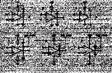
Which one of these bypass configurations
would be (do you) prefer? Why? I've seen
all of these in various schematics, but I
have no clue which one would be prefered
and why.
[I have larger version of this picture...
Let's see how this one turns out.]
Attachments
this time I think I got it right....
An externally hosted image should be here but it was not working when we last tested it.
I see. So If I have a supply with Vcc and 0 rails and
a virtual ground driver at Vcc/2 one might as well
put the bypass between Vcc and 0 rather than Vcc
and Vcc/2 and also Vcc/2 and 0?
What's the reason for a decoupling resistor then?
It's common in rf circuitry, but I've seen it in a lot
of amp and guitar fx schematics as well. A poor
mans regulator? Wouldn't it kill dynamics? Even
with only 0.1uF and 47Ohms the treshold is at
about 33 kHz.
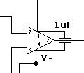
What about putting bypass cap. as in A compared
to B? Does that really make any difference?
- Status
- This old topic is closed. If you want to reopen this topic, contact a moderator using the "Report Post" button.

