Hi,
First of all, this is my first post here. I am fairly new in amp building. The LM3875 from Peter (audiosector.com) will be my first project.
As background in electronics, I've done a few guitar fx pedals but nothing more.
So, I didn't receive my kit yet but I am trying to put all the pieces in the right place before I start. I haven't decided yet but I maybe planning to separate the power supply from the amp.
That is where my question goes... is it necessary to run the ground (protective earth) from the power supply to the amp chassis? see the picture
I've seen setup that this is not done but I've read somewhere that it should be there... I'm confuse.
Thanks all for your input,
yan
Attachments
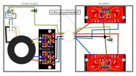
...is it necessary to run the ground (protective earth) from the power supply to the amp chassis?
It sure is. For one thing, a metal enclosure is not a fully effective RF (radio frequency) shield unless it's grounded ("bonded to ground"). For another, electrical codes require that any metal accessible to a user must be grounded for safety. I don't know what the actual legal liability situation might be in Canada, but I can't think you'd want to be a test case. And then, kids do get into everything.
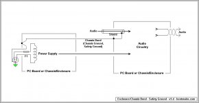
Posted below is my understanding of "the way you do it." The chassis bond located right next to the audio input might appear exactly wrong at first, but it's from Douglas Self's "Audio Power Amplifier Design Handbook," page 402. He says:
"Mains/chassis ground will need to be connected to the power amplifier at some point. Do not do this at the transformer centre-tap as this is spaced away from the input ground voltage by the return charging pulses, and will create severe groundloop hum when the input ground is connected to mains ground through another piece of equipment.
"Connecting mains ground to starpoint is better, as the charging pulses are excluded, but the track resistance between input ground and star will carry any ground-loop currents and induce a buzz.
"Connecting mains ground to the input ground gives maximal immunity against groundloops."
(Also see his related comments on page 405, discussing so -called "ground lift" methods.)
If you don't know, Mr. Self is a well known and much-published guru in the audio world, so I'd say taking his advice can't steer you far wrong.
.
Attachments
Thanks for your response. This clears it up. As well as the handbook from Douglas Self. Great info in this book!
I will run that wire.
That brings me to my next question, will a 4 pin XLR connector do the job? I like the fact that it locks pretty well. And I guess that if it's labelled right no one will plug is headphone there. But who knows, might be better to go with a DIN connector? Something else?
And any suggestions about if I should use only 1 chassis mount connector with a non-removable cable or 2 chassis mount with a removable cable. My guess is less connection is better ?
Thanks again!
yan
From page 411 of the Audio Power Amplifier Design Handbook "either a balnce input or ground cancelling output will be required", can nyone explain what is a"ground cancelling output" and how to implemen that ?
There's some discussion in "Self on Audio," chapter 8.
.
...will a 4 pin XLR connector do the job? I like the fact that it locks pretty well. And I guess that if it's labelled right no one will plug is headphone there. But who knows, might be better to go with a DIN connector? Something else?
And any suggestions about if I should use only 1 chassis mount connector with a non-removable cable or 2 chassis mount with a removable cable. My guess is less connection is better ?
My 2 cents:
Before anything else, face reality: if it can be done wrong it will be, and that certainly includes plugging the wrong wire into the wrong hole. In fact, such an easy mistake is practically an engraved invitation.
In accordance with the same principle, it you have a 5 foot cable permanently attached, you'll immediately need a 6 foot cable.
XLR connectors scream what they are to the whole world, so mistakes are at least minimized. Sometimes there's wisdom in doing what's expected.
"DIN Connector" is a broad term, you have to specify: DIN connector - Wikipedia, the free encyclopedia
None of which is to suggest that there's anything wrong with better, and fewer and tighter connections are always better. But what's better enough to matter? XLR connectors, or just plain ol' 1/4-inch jacks (3.5mm consumer/computer), are used on amps costing as much as a car, so how bad can they be?
.
Last edited:
The way Peter builds the Patek Amp v2 is to create a star ground between the amp boards. This star ground has 5 wires, OG amp1/OG amp2/Chassis and from the PSU PG+/PG-. It is unclear how the mains ground/earth is connected. I advise an additional wire for this connection.
DC Cable V+/V-/PG+/PG-/chassis.
DC Cable V+/V-/PG+/PG-/chassis.
.
In the illustration in post #3 I omitted the second connection made to the audio cable shield, the arrow. This connection might be obvious, but "obvious" is a relative concept, so I'd better correct that error. Doing so here.
At the same time, for reference and clarity, I might as well post the by-now-infamous figure 14.1 from Douglas Self's "Audio Power Amplifier Design Handbook." Here I've highlighted the significant conductors in green.
Translating from Mr. Self's British English--assuming I understand it myself:
"Main's Earth" is a 10-foot steel rod driven into the ground near a building's electric meter. All third-prong conductors (bare or green) ultimately connect to this single point. This is not within an electronics tech's authority, it's done by electricians, who call it just ground--or earth, if they're foreigners. There is no common name for it because most people don't know it exists.
"Protected Chassis Earth" is commonly called safety earth, safety ground, or chassis ground. It's what I insist on calling the chassis bond because that's what it is. Bare or green wires going to the exterior ten-foot rod do not have "connections," rather, they're "bonded," which by implication means bonded to ground.
Electronic circuits have a circuit ground, which is bonded to the chassis ground, which in turn is bonded to the exterior earth ground.
.
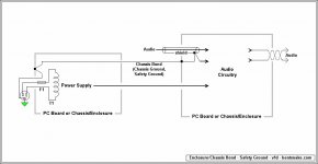
Attachments
Last edited:
The Mains third wire is "Protective Earth". It is connected to Neutral @ the distribution board..........................Translating from Mr. Self's British English--assuming I understand it myself:
"Main's Earth" is a 10-foot steel rod driven into the ground near a building's electric meter.
green/yellow insulation or green yellow sleeving over the bare copper wire.All third-prong conductors (bare or green)
We call it "earth"ultimately connect to this single point. This is not within an electronics tech's authority, it's done by electricians, who call it just ground--or earth, if they're foreigners.
Virtually every adult and most teenagers will be very aware and know what "earth" means in the electrical sense. We have schools here that do a good job.There is no common name for it because most people don't know it exists.
Forget about that "rod". In most situations in the UK it does not exist."Protected Chassis Earth" is commonly called safety earth, safety ground, or chassis ground. It's what I insist on calling the chassis bond because that's what it is. Bare or green wires going to the exterior ten-foot rod do not have "connections," rather, they're "bonded," which by implication means bonded to ground.
Electronic circuits have a circuit ground, which is bonded to the chassis ground, which in turn is bonded to the exterior earth ground.
.
The "connection" you refer to, is done at the distribution board.
THE GREEN HIGHLIGHTED ROUTE on D.Self's extract.
The route you have shown is very likely to include small cross section wiring and small soldered joints. These may not be robust/reliable enough to pass the FAULT CURRENT, approaching and even exceeding 1000Apk (1kApk) to Protective Earth (PE) if and when that mains wiring fault occurs.
What you have shown NEEDS a dedicated high current wiring route from Main Audio Ground to CHASSIS. This connection does not need to go back to the same mechanical fixing that locates the PE to CHASSIS.
Your GREEN ROUTE and your wiring description is potentially hazardous !
Last edited:
...The Mains third wire is "Protective Earth". It is connected to Neutral @ the distribution board....Forget about that "rod". In most situations in the UK it does not exist...
I think it's instructive to realize that neutral and ground are not the same thing. Your distribution board (the breaker panel) might have no obvious connection to ground, it might appear to electrically float, but it does not float, it's grounded--literally connects to ground, the planet Earth--as I described.
Apparently the UK does not like DIYers doing electrical work. I say that because information is not easy to come by. But this page might be of interest: Richard Coombs Electrical Safety Dunblane
The second illustration on the page shows the ground rod I spoke of.
After that, my purpose in post #11 was not to discuss electrical engineering, but to clarify Douglas Self's grounding recommendations.
But I really don't see the point of your post at all. What is it you're recommending?
THE GREEN HIGHLIGHTED ROUTE on D.Self's extract.
The route you have shown is very likely to include small cross section wiring and small soldered joints. These may not be robust/reliable enough to pass the FAULT CURRENT, approaching and even exceeding 1000Apk (1kApk) to Protective Earth (PE) if and when that mains wiring fault occurs.
What you have shown NEEDS a dedicated high current wiring route from Main Audio Ground to CHASSIS. This connection does not need to go back to the same mechanical fixing that locates the PE to CHASSIS.
Your GREEN ROUTE and your wiring description is potentially hazardous !
I'm sure you know that there is no "my" circuitry in the posted image. It's Douglas Self's grounding recommendation, unedited except for the green highlighting. If you think Mr. Self's grounding methods are wrong, then I suppose you should communicate that to him (not to me).
But more to the present case, and again, what do you recommend instead?
.
Last edited:
The Mains third wire is "Protective Earth". It is connected to Neutral @ the distribution board.
On the other hand, this, at least, could be instructive.
Obviously (I'd supposed) post #11 was my attempt to define and/or clarify Douglas Self's "Mains Earth" and "Protected Chassis Earth" for those who don't live in the UK--which includes me.
If I got these wrong then I'd be very glad to be corrected.
But we all agree that technical terms matter, and they matter a lot. Your "Protective Earth" is not the same as either of the terms Mr. Self uses, so...which is what?
.
Last edited:
Yes, you are confused.
Protective Earth is the correct term here in the UK.
It seems it is also understood in many other Countries around the world.
Before you try to tell us UK residents how our UK Mains is connected, you should learn how to differentiate between Neutral and Earth and Protective Earth and Main Audio Ground.
I have deliberately NOT included "ground" in that list because that word just impedes understanding and causes confusion.
And YOU failed to notice that the FIRST pic shows the NEUTRAL to Protective Earth connection at the distribution board.I think it's instructive to realize that neutral and ground are not the same thing. Your distribution board (the breaker panel) might have no obvious connection to ground, ........................ But this page might be of interest: Richard Coombs Electrical Safety Dunblane................
.
This is OUR UK PROTECTION. It is what blows our fuses when a mains fault tries to endanger users.
Yes, you are confused.
Protective Earth is the correct term here in the UK.
It seems it is also understood in many other Countries around the world.
Before you try to tell us UK residents how our UK Mains is connected, you should learn how to differentiate between Neutral and Earth and Protective Earth and Main Audio Ground.
I have deliberately NOT included "ground" in that list because that word just impedes understanding and causes confusion.
Well then...so you intend to convey...no information at all? So I guess fine, so suits you = suits me.
.
...you should learn how to differentiate between Neutral and Earth and Protective Earth and Main Audio Ground....
In a sidebar, just to mention it, what those terms mean in the UK is exactly the question I was asking. I'm putting you down for a reply of "go look it up."
Which admittedly is sound advice, but not at all helpful, since I'm already trying to do that.
.
Last edited:
'AndrewT' has an excellent understanding the situation. That stake in the garden has nothing to do with safety during 'fault' (short circuit) conditions. During a fault it's the Safety Ground/Protective Earth/EGC conductor's connection to the Neutral that causes the circuit breaker to trip. From a audio system, AC power quality prospective that stake in the garden adds nothing.
Moderators Take Heed
.
Breakers trip when current flow through them exceeds their rating, it doesn't matter whether the current flow is to neutral, ground, or the Fiji Islands. Ground Fault Breakers are sensitive to current flow to ground, they depend on that stake in the garden to function.
But more importantly, I urge any moderator to delete this entire thread, and I'm sure not kidding.
This thread has become downright dangerous due to the misinformation being put forth. No I'm serious, some of these notions can get somebody killed. For instance, a home handyman trying to use some of this information might disable all the ground fault breakers in a residence, with possibly fatal consequences. This is no time for fooling around, get rid of this thing.
.
.
Breakers trip when current flow through them exceeds their rating, it doesn't matter whether the current flow is to neutral, ground, or the Fiji Islands. Ground Fault Breakers are sensitive to current flow to ground, they depend on that stake in the garden to function.
But more importantly, I urge any moderator to delete this entire thread, and I'm sure not kidding.
This thread has become downright dangerous due to the misinformation being put forth. No I'm serious, some of these notions can get somebody killed. For instance, a home handyman trying to use some of this information might disable all the ground fault breakers in a residence, with possibly fatal consequences. This is no time for fooling around, get rid of this thing.
.
Last edited:
- Status
- This old topic is closed. If you want to reopen this topic, contact a moderator using the "Report Post" button.
- Home
- Amplifiers
- Chip Amps
- LM3875 separate chassis ground