I'm sure that everyone knows that breakers trip when current flow exceeds their capacity. But fault current flows back to the power company Neutral. This current has little interest in that stake in the garden. In fact if the S.G./P.E. conductor is incorrectly connected to that stake rather than the power company Neutral, it's unlikely that the breaker will quickly trip (in fact it may never trip).
Another Plea to Mods
I doubt that you know everyone, so you can't say what they know or don't. But it's safe to say that some hereabouts have no knowledge of how circuit breakers work--which for crying out loud is not hard.
Doesn't the name tell you anything? GROUND FAULT breaker. These trip when excessive current flows to ground. This is in addition--that's in addition--to tripping under other overload conditions.
This ground fault protection assumes that the fault current's path to ground (not neutral) is though you. Protecting you against electrocution is its purpose in the first place.
To do this, the ground fault breaker works together with the garden stake you so mercilessly ridicule. You really should have more appreciation for something that could save your life at any instant.
But happily, the garden stake is professional to the core. It does its job quietly and efficiently, caring for neither complaint nor praise, your last line of defense against smelling yourself burning whether you like it or not.
But unlike the garden stake, ah gits weary. I implore you who consider yourselves experts to stay well away from anything electrical. Have you considered the joys of gardening? With which counsel I leave you to your opinions.
Only first again urging some mod, any mod, to delete this thread before somebody kills themselves. I'm not kidding, this is dangerous stuff.
.
I'm sure that everyone knows that breakers trip when current flow exceeds their capacity. But fault current flows back to the power company Neutral. This current has little interest in that stake in the garden. In fact if the S.G./P.E. conductor is incorrectly connected to that stake rather than the power company Neutral, it's unlikely that the breaker will quickly trip (in fact it may never trip).
I doubt that you know everyone, so you can't say what they know or don't. But it's safe to say that some hereabouts have no knowledge of how circuit breakers work--which for crying out loud is not hard.
Doesn't the name tell you anything? GROUND FAULT breaker. These trip when excessive current flows to ground. This is in addition--that's in addition--to tripping under other overload conditions.
This ground fault protection assumes that the fault current's path to ground (not neutral) is though you. Protecting you against electrocution is its purpose in the first place.
To do this, the ground fault breaker works together with the garden stake you so mercilessly ridicule. You really should have more appreciation for something that could save your life at any instant.
But happily, the garden stake is professional to the core. It does its job quietly and efficiently, caring for neither complaint nor praise, your last line of defense against smelling yourself burning whether you like it or not.
But unlike the garden stake, ah gits weary. I implore you who consider yourselves experts to stay well away from anything electrical. Have you considered the joys of gardening? With which counsel I leave you to your opinions.
Only first again urging some mod, any mod, to delete this thread before somebody kills themselves. I'm not kidding, this is dangerous stuff.
.
Last edited:
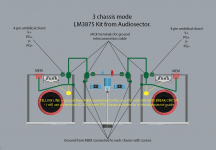
Three chassis setup: LM3875 kit from audiosector.
Hello,
I have been waiting some days to write this post, I´ve tried to read in this thread and other threads to understand how to set up correct saftey ground for my 3 chassis setup.
I have used quite some time with my LM3875 kit from Audiosector.
I`m in the progress of making a a three chassis setup:
Two power supply´s; each transformer with PSU board in separate chassis.
+
The main chassis with the main amplifer boards and an attenuator.
I am now posting in this thread because I want to confirm that I am assembling my amplifiers correctly ( especially taking the safety ground into concern )
1. I will run a 4 pin umbilical chord ( bought from a company in the UK ) from each power supply to main amp.
2. I will run a 5th ( safety ground ) cable from each power supply to the main amp. I have now four jack connectors ( for chassis mount ) and two shorter patch cables from a local guitar shop.
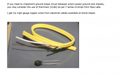
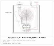
3. I will install a ground break circuit within each power supply. I will install a thermisor (CL60) as shown in attachment2.
Attachment 1 is how I will assemble my amplifier setup.
good_ground_9 is my source of understanding this setup visually. - taken from this thread: http://www.diyaudio.com/forums/power-supplies/115698-understanding-star-grounding-6.html
Everything said OK ?
ONE LAST IMPORTANT QUESTION:
WILL I NEED TO USE A THICKER GAUGE CABLE FOR SAFETY GROUND BETWEEN EACH POWER AND MAIN AMP CHASSIS ; OR CAN I USE THE STOCK SIGNAL PATCH CABLE FROM THE LOCAL GUITAR SHOP?
Link to audiosector guide: http://www.audiosector.com/nigc_kit-users_guide.pdf
Hello,
I have been waiting some days to write this post, I´ve tried to read in this thread and other threads to understand how to set up correct saftey ground for my 3 chassis setup.
I have used quite some time with my LM3875 kit from Audiosector.
I`m in the progress of making a a three chassis setup:
Two power supply´s; each transformer with PSU board in separate chassis.
+
The main chassis with the main amplifer boards and an attenuator.
I am now posting in this thread because I want to confirm that I am assembling my amplifiers correctly ( especially taking the safety ground into concern )
1. I will run a 4 pin umbilical chord ( bought from a company in the UK ) from each power supply to main amp.
2. I will run a 5th ( safety ground ) cable from each power supply to the main amp. I have now four jack connectors ( for chassis mount ) and two shorter patch cables from a local guitar shop.
3. I will install a ground break circuit within each power supply. I will install a thermisor (CL60) as shown in attachment2.
Attachment 1 is how I will assemble my amplifier setup.
good_ground_9 is my source of understanding this setup visually. - taken from this thread: http://www.diyaudio.com/forums/power-supplies/115698-understanding-star-grounding-6.html
Everything said OK ?
ONE LAST IMPORTANT QUESTION:
WILL I NEED TO USE A THICKER GAUGE CABLE FOR SAFETY GROUND BETWEEN EACH POWER AND MAIN AMP CHASSIS ; OR CAN I USE THE STOCK SIGNAL PATCH CABLE FROM THE LOCAL GUITAR SHOP?
Link to audiosector guide: http://www.audiosector.com/nigc_kit-users_guide.pdf
Attachments
I think there are two faults in the design.
PG+ and PG- should be kept separate and are only joined via the ground plane on the Audiosector amp boards. You can't accomplish this by connecting the PSU boards to the chassis.
The ground leads connecting the three chassis should be either permanent or added to the (low) power cables, which means a five wire cable (V+,V-,PG+,PG- and Chassis Ground).
Last edited:
Thanks ;-)
Now I think I got it...
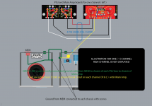
See attached drawing.
Will use a permanently attached thicker gauge cable between the two PSU chassis to Main amp for Safety Ground.
Will install a ground break circuit for each channel within main chassis like shown in the attached drawing.
Now I think I got it...
See attached drawing.
Will use a permanently attached thicker gauge cable between the two PSU chassis to Main amp for Safety Ground.
Will install a ground break circuit for each channel within main chassis like shown in the attached drawing.
Attachments
Indeed, but it may work. It may work very well and maintain adequate safety to protect Users from a catastrophic fault.CL60 as a GLB, there is also no info in the datasheet for it to be used in such a way
Pass has the lonely CL60 shown as the Disconnecting Network (DN) device in some of their schematics.
I have referred to this a few times and to the fact that I have not seen any test of the effectiveness of a sole CL60 as the DN device.
The user relies on the CL60 passing Fault Current to the Protective Earth and surviving long enough till the Mains fuse ruptures and the arc extinguishes.
I have reported how I tested the bridge rectifier used as the DN device.
Without any proper electrical qualifications, I concluded that it passed for this Fault Current to PE duty.
The resistor/diodes/capacitor GLB has the advantage of freedom of design. Use diodes with a high surge current specification. The resistor power can be calculated with the forward voltage of the diodes.
The CL60 may work with a low power PSU and a 500mA mains fuse but I am only guessing here.
The CL60 may work with a low power PSU and a 500mA mains fuse but I am only guessing here.
GROUND BREAK CIRCUIT
I have had my LM3875 project on hold for a while.
I´m NOT a professional when it comes to electronics. - I´ve done some amp kits before; but this LM3875 kit has been the most difficult project for me so far.
I´m crossing fingers someone out there with more knowledge than me can help me to design the correct ground break circuit for my three chassis LM3875 amplifier.
After a short ( very short ) google search I do not find any answers about the purpose of using a ground break circuit.
1.
What is the purpose of a ground break circuit?
- Is it to eliminate or break ground loops?
- or has it more to do with safety issues?
2. What information do you need to help me to design the correct ground break circuit?
PS: there is no purpose from my side to hijack this thread, but since I have posted in this thread before I find it correct to use the same thread to ask for help.
A mains powered device must be safe, both to you the Builder and any operators that cares to touch the controls and/or cables attached to it.
For us as amateur Builders, we have to build to ClassI standard.
This requires us to use a 3wire mains connection with the PE wire mechanically connected to the main Chassis.
This is what blows the Mains fuse if the Chassis or anything attached to the chassis becomes Live.
All exposed conductive parts must be connected to the Chassis.
This is what makes control knobs, cables and terminals safe to touch. The exposed parts of the terminals, etc are usually connected to Audio Ground and that audio ground needs to be connected to chassis.
Some amplifiers have the audio ground connected to chassis directly and they do not hum.
But many do hum and this is often due to a current loop in the grounded wiring.
It is the connection from Audio Ground to Chassis that can benefit from a current attenuating resistor.
BUT!!!!
this connection may during fault conditions have to pass FAULT CURRENT approaching kilo amperes until the mains fuse ruptures.
It is the requirement to pass kA that demands something more than a resistor for this attenuating device.
You must use very high current Power Diodes to pass the Fault Current to the chassis and thence to PE and back to the mains distribution board.
Pass and some of his followers use a Power Thermistor instead of a resistor and assume this can pass Fault Current until the mains fuse ruptures. I have still not seen any evidence that this assumption has been tested despite me repeatedly bringing the Forum's attention to the potential risk.
I´m quite sure I understand what you´re saying.
I want my DIY build to be as safe as possible.
This is also why I stopped my building process; because hints and answers I got to questions I had were going in straight opposite directions.
Making a three chassis setup did not make my project any more easy to complete.
I will need a ground break circuit for my design.
- Anyone that know how to do that?
do you need one or three or none? assemble one with a direct connection from Audio Ground to Chassis.
Power one up and measure the hum+noise at the output.
Couple up an interconnect and source and see if the H+N increases. If acceptable build two copies.
If not acceptable come back and we will try to help you identify the problem/s.
Power one up and measure the hum+noise at the output.
Couple up an interconnect and source and see if the H+N increases. If acceptable build two copies.
If not acceptable come back and we will try to help you identify the problem/s.
I need one amplifier.
Initially I wanted to make a dual mono amplifier.
I´ve stuck to that idea til now.
I got a new approach. Making monoblocks. See attached jpeg file!
- this idea was actually mentioned by you AndrewT before I started building this amplifier in another thread.
OK. I want to stick to the idea of using two power transformers.
One PSU for each channel.
Is it easier for me to build monoblocks at this stadium?
* I will not need a umbilical chord.
** No ground cable that is fixed between each of the three chassis.
*** I can fasten the LM3875 chip to the front panel (10mm ) of each monoblock.
**** I can use my Quad 44 pre until I get the courage to do a buffered passive pre-amp DIY project.
is this doable? and is my sketch correctly set up?
thanks ! ;-)
Attachments
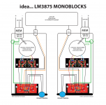
here´s my final setup.
no umbilical chord.
no ground break circuit
no CL60
two of these units:
monoblocks.
will use star ground and a MEM with 5AT fuse.
- anyone know how to find instructions on how to delete attachments easily? can't find any. I have too many illustrations on my LM3875 kit building process.
no umbilical chord.
no ground break circuit
no CL60
two of these units:
monoblocks.
will use star ground and a MEM with 5AT fuse.
- anyone know how to find instructions on how to delete attachments easily? can't find any. I have too many illustrations on my LM3875 kit building process.
Attachments
My view on protective earth is ALWAYS use a complete metal to metal path from start to end, if you get problems then you have to solve them... but I never break my protective earth connection, one day it might save someone's life.
Simple guide for UK mains...
http://www.gcsescience.com/pe35.htm
Simple guide for UK mains...
http://www.gcsescience.com/pe35.htm
Last edited:
The PE can connect locally to where it enters the chassis.here´s my final setup.
no umbilical chord.
no ground break circuit
no CL60
two of these units:
monoblocks.
will use star ground and a MEM with 5AT fuse.
- anyone know how to find instructions on how to delete attachments easily? can't find any. I have too many illustrations on my LM3875 kit building process.
Where the chassis is made from many panels, one can add safety connections from panel to panel. If there is a risk that a panel to panel assembly could develop significant resistance (corrosion) over time then an added panel to panel safety connection becomes mandatory.
The safety connection from the amplifier to the chassis can be made locally. It does NOT need a long wire back to the PE connection at the mains input.
- Status
- This old topic is closed. If you want to reopen this topic, contact a moderator using the "Report Post" button.
- Home
- Amplifiers
- Chip Amps
- LM3875 separate chassis ground