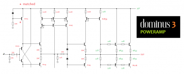
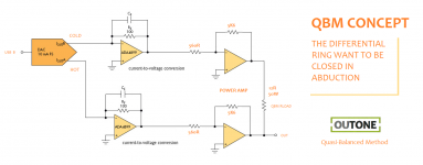
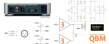
Here's an example I have on the bench at the moment.
Gain is 23times (+27.2dB)
Input is 30kHz sqw ~20mVpp
Output is 500mVpp
The load is only the the output Zobel consisting of 4r8+45nF There is no output current, since there is no output load.
The supply rail ground is spread around the PCB (a terrible way to arrange the power ground)
I can measure the ground trace voltage bounce as a glitch that coincides with the falling and rising edges of the sqw test signal.
Near the attachment point of the scope probe ground lead, the bounce is unmeasuable on a 2mV/div scale.
As I move in either direction from the reference point, the glitch voltage increases.
At one end near the -ve side devices and their decoupling capacitors, the voltage glitch has risen to ~35mVpk and ~0.2us wide for the half wave pulse, on the -ve side the voltage glitch has risen to ~70mVpk, again about 0.2us wide.
These worst glitches are very close to where the front end gets it's power and power ground. Yes, the front end is suppled from a ground rail that bounces by >+60mVpk and >-22mVpk.
This is typical of many amplifiers that have a power ground that spreads around the PCB over many inches of trace length.
The amplifier, whether it's a chip amp or a discrete, tries to amplify what it sees as an input signal and uses a ground reference that modulates that signal. The input signal is the difference between the Hot and Cold terminals.
The amplifier is working with "signals" that are in the MHz range, when there is a fast transient at the input.
Note the VERY low level signals I was using. If that was a sinewave of 176mVac at the output, that is equivalent to <4mW into 8r0. That is roughly -46dB ref maximum power.
One way to reduce this effect is to attenuate the very fast transients, both audio file transients and interference transients.
You can set the input RF attenuator to F-3dB = 10MHz or to 20kHz or anywhere in between of your choosing.
Last edited:
Yes,
the last dozen or so posts are talking about a low gain amplifier, transient currents and supply rail decoupling.
I gave a real example of what goes on "inside" a PCB, especially one that has not taken trace impedance of LONG traces into account when trying to get local decoupling to work.
This question was asked:
and this statement was postedis that even remotely audible ?
Supply rail decoupling is a good engineering/design practice, in particular for high-current op-amps, which is what an LM3886 is.
Last edited:
This Forum has a post with a link to a (three different) speakers test that showed more than 5times the current passing to the reactive speaker load than what the rated speaker impedance would indicate for a resistor/dummy load.
Can you give the links ?
Similar requirements were established by Ottala.
Self pointed out that it is for unrealistic audio signals and then much exaggerated.
Reading that test report made me change MY design procedure from allowing double the output current to triple the output current.
i.e. a 100W into 8ohms needs to drive 40Vpk and 5Apk into a 8r0 resistive load AND must be able to drive 15Apk into a reactive load, without the PSU or the amplifier collapsing.
D. Self should say 10 Apk is largely sufficient.
For an active loudpseaker, it is even less for each driver.
For a DIY design 15A peak is not that overkill. Hell my first power amp, done when I was 20 was 50W and 40A peak. Was not totally stable, but could put out 75W at MW frequencies. I miss being young and stupid sometimes.
This does link to the argument, should you make the speaker an easy load to drive or expect the amplifier to be able to drive a 6" nail if required.
This does link to the argument, should you make the speaker an easy load to drive or expect the amplifier to be able to drive a 6" nail if required.
hmm and what about those competition woofers for cars, 2 ohm rated, and can take past a killowatt of RMS power.
what kind of peak current would one be expecting ?
like.. for a "tiny" voltage swingof say... 40 volts , You would expect a current spike of what , 100 A range ? or..even more ?
what kind of peak current would one be expecting ?
like.. for a "tiny" voltage swingof say... 40 volts , You would expect a current spike of what , 100 A range ? or..even more ?
The 0r1 test is effectively a "short circuit" test.
This will give information on survivability in event of abuse and check for effectiveness of current limiting and/or IV limiting if fitted.
That is very different from finding how much unclipped output the amplifier can drive into a load.
This will give information on survivability in event of abuse and check for effectiveness of current limiting and/or IV limiting if fitted.
That is very different from finding how much unclipped output the amplifier can drive into a load.
The 0r1 test is effectively a "short circuit" test.
This will give information on survivability in event of abuse and check for effectiveness of current limiting and/or IV limiting if fitted.
That is very different from finding how much unclipped output the amplifier can drive into a load.
0.1 Ohm in series with the load
For unity gain operation with LM3886 take an look on linked schematic and look around for example U1 (R5 and R4 are crucial! For R6 use 22K) :
http://www.diyaudio.com/forums/chip-amps/233411-batomm-amp-lm-bridge-consider-try.html
Output Zobel, who use that anymore with LM3886?
You need just R1 in arrangement as show on schematic.
http://www.diyaudio.com/forums/chip-amps/233411-batomm-amp-lm-bridge-consider-try.html
Output Zobel, who use that anymore with LM3886?
You need just R1 in arrangement as show on schematic.
He meant as a sole load to find the peak transient current to prove effectiveness of protection/s.0.1 Ohm in series with the load
- Status
- This old topic is closed. If you want to reopen this topic, contact a moderator using the "Report Post" button.
- Home
- Amplifiers
- Chip Amps
- LM3886 AS POWER BUFFER


