.
Oh me & oh my. I greatly respect your intention to mess around with the thing, it is, after all, what these forums are for. And I really hate to be a wet blanket...but...
The spec for the rail splitter is 20ma out. It's for preamps and mixers and such, not nearly enough for, for instance, a 20 watt amp.
(watts = volts x amps = VA)
The LM317 or similar would certainly drop 58 volts to, say, 30 volts. Though better might be the LM150 with its 3 amp output (whichever you use, heat sink it!). So sure, single supply, why not.
Do be aware that 58 volts might or might not knock you across the room, but it sure can give you a serious tingle...or worse. Be safe, unplug.
.
Yes I have to be careful. But would it not be the same case with +/- 29V, again it is the potential difference that counts isn't it?
30vdc each rail?
No, 30 volts total, since the subject is a single, not dual, supply.
Yes I have to be careful. But would it not be the same case with +/- 29V, again it is the potential difference that counts isn't it?
As above, no +/- just 30 volts total. I thought the subject was a single supply, not dual? If I missed something, oops.
.
Ok, I am going with 44V single supply, is that too much? That is +/- 22v Dual. From the spec it looks fine?
Well sure, it says right there on page 1 of the data sheet: Wide supply range 16V-60V. Strictly speaking you could use 58 volts, but look at the graph on page 3, "Power Output vs Supply Voltage."
If you don't know, with single-supply +44 volts applied you're actually running the op amp at a virtual +/- 22 volts.
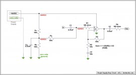
Referring to the TI data sheet, the circuit on page 2, "Typical Single Supply Operation."
R1 and R2 form a voltage divider network with +22 volts appearing at R3 (because R1 and R2 are equal).
This puts the innards of the op amp at +22 volts. One result is that this same +22 volts appears at output pin 7. And so does the audio output. The audio output, which should be AC, is at this point modulated DC. The audio signal voltage is riding on a steady-state DC voltage.
(which by the way is similar to the way radio works, the audio signal rides on a carrier wave)
But C5 blocks the DC component, feeding only AC on to the next stage.
Realize that this virtual +/- 22 volts only works for this one op amp in this one circuit, because you wired it up that way. Other components, in other circuits, don't want the audio signal coming in accompanied by +22VDC, and will indicate their displeasure by burning out.
This is (in part) what C1, C3, and C6 are for. They isolate the entire single-supply circuit from the rest of the world, keeping voltages as they should be. These (or similar) capacitors are mandatory with single supply circuits.
In an addendum, of course if you have several single-supply stages in series, then you only have to isolate the group, not each stage individually. And of course you still might use capacitors for purposes other than blocking DC.
.
Last edited:
Well sure, it says right there on page 1 of the data sheet: Wide supply range 16V-60V. Strictly speaking you could use 58 volts, but look at the graph on page 3, "Power Output vs Supply Voltage."
If you don't know, with single-supply +44 volts applied you're actually running the op amp at a virtual +/- 22 volts.
Referring to the TI data sheet, the circuit on page 2, "Typical Single Supply Operation."
R1 and R2 form a voltage divider network with +22 volts appearing at R3 (because R1 and R2 are equal).
This puts the innards of the op amp at +22 volts. One result is that this same +22 volts appears at output pin 7. And so does the audio output. The audio output, which should be AC, is at this point modulated DC. The audio signal voltage is riding on a steady-state DC voltage.
(which by the way is similar to the way radio works, the audio signal rides on a carrier wave)
But C5 blocks the DC component, feeding only AC on to the next stage.
Realize that this virtual +/- 22 volts only works for this one op amp in this one circuit, because you wired it up that way. Other components, in other circuits, don't want the audio signal coming in accompanied by +22VDC, and will indicate their displeasure by burning out.
This is (in part) what C1, C3, and C6 are for. They isolate the entire single-supply circuit from the rest of the world, keeping voltages as they should be. These (or similar) capacitors are mandatory with single supply circuits.
In an addendum, of course if you have several single-supply stages in series, then you only have to isolate the group, not each stage individually. And of course you still might use capacitors for purposes other than blocking DC.
.
Thank you for the explanation.
Looking at the graph of Output vs Supply voltage I see that for 44V single supply I am going to look at 22V on the graph, for this I get about 20W, so? I am sorry I am not able to get your point. I am assuming we are good at about 44V?
One question - why don't I have similar problem in a dual supply circuit. The voltage is halved but not absent, should we not have to use decoupling capacitors in this case also?
Last edited:
...should we not have to use decoupling capacitors...
Very unfortunately, some terms have been tossed around so much that they no longer have specific meaning, and this applies especially to decoupling and bypass capacitors. Please explain what you mean by "decoupling capacitors." Use the circuit in post #28, if it applies.
I personally adhere to what appears the be the standard at Texas International. They place bypass capacitors at the op amp terminals, and decoupling capacitors in the power supply.
Or there are also DC blocking capacitors, did you mean these?
.
Pardon my ignorance - I kind of think that blocking capacitors as those that block dc from entering other parts of the circuit by providing high resistance path and bypass capacitors as those that prevent ac from entering other parts of the circuit by provide low impedance paths.
My question is should will we not be needing these capacitors in a dual supply circuit also? I have been trying to understand how single supply is causing the need for these capacitors while dual supply escapes the ac riding on dc logic.
I have been trying to understand how single supply is causing the need for these capacitors while dual supply escapes the ac riding on dc logic.
It's not logic, it's fact. Not a metaphor, that's what really happens.
But before anything else, a little bit more about single-or-dual.
Nearly all audio chips, except for some newer ones, run on dual voltages. That is, they need both positive and negative voltages from a power supply to operate. It's impossible to run these chips on a single voltage, that's just the way they're designed.
In the case of a "single supply" what you do is go through some contortions(!) to create a virtual ground, and by this means create virtual positive and negative voltages that will run the chip. The same positive and negative voltages you'd get from a dual supply in the first place.
All of which is to say that you take the long way around, adding components and complexity, to get to the same place by a more difficult route. Crossing the street by way of Chicago.
Not to say this is necessarily bad, just to point it out as a fact. After all, in for instance a car radio, all you have to work with is a single 12 volts. So you do what you gotta do.
Or like, for instance, if you only had 44 volts to work with. All sameO.
.
I have been trying to understand how single supply is causing the need for these capacitors while dual supply escapes the ac riding on dc logic.
In a dual supply the amplifier can make the speaker one move out by making the output more positive (towards the +22) , and bring it back and move it in by making it more negative (towards the -22) Not much actually happens with ground, it's the middle between two supplies, and the amp can move on either side of it, like a number-line in grade school, when negative numbers were being introduced.
With a single supply, the speaker still needs to move in and out, so we now call +22 "ground" , +44 now acts like the positive rail, and zero (actually no volts) the negative rail.
So with the single supply, the output is sitting at +22V. You need the big output capacitor to block the DC, and only let the AC (I.E., the music) to the speaker.
Thank you 6L6, I finally got it !
")
I would suggest you to try the integrated amplifier IC
CS6A4983
More about this amplifier IC is available in
http://www.amazon.com/seeedstudio-Current-Assisted-Amplifier-CSEVB6101R3/dp/B010N89AVI
and
https://www.youtube.com/watch?v=ZBeniBaiUFw
In Class A operation, the dynamic range is almost as wide as the supply voltage.
CS6A4983
More about this amplifier IC is available in
http://www.amazon.com/seeedstudio-Current-Assisted-Amplifier-CSEVB6101R3/dp/B010N89AVI
and
https://www.youtube.com/watch?v=ZBeniBaiUFw
In Class A operation, the dynamic range is almost as wide as the supply voltage.
I've been wondering how long it would take to see an amp like that. Congrats!...CS6A4983 More about this amplifier IC is available in Current Assisted Class A Linear Amplifier | Seeedstudio...
- Status
- This old topic is closed. If you want to reopen this topic, contact a moderator using the "Report Post" button.
- Home
- Amplifiers
- Chip Amps
- Which amp for least distortation (10W + 10W) under $50. No class D please.