Since you ask, consider that these little black chips don't exist in a vacuum. The factory has to provide not only a chip, but the circuit it works in.
The data sheet schematic was created by the same team of engineers who created the chip in the firs place. Keyword "team," these are teams of several senior and junior engineers checking each other's work. They use testing equipment that costs tens of thousands of dollars. Take into account the fact that Texas International, for instance, doesn't hire the bottom ten percent of the class, those guys are designing toasters.
Consider prototypes and testing. Humans can't build these little chips, it takes a machine. So after everybody's best ideas have been worked out on paper, special machines create a few prototype chips for testing. These machines cost more tens of thousands of dollars.
After long human/machine testing, prototyping, and testing again, at last the micro-accurate production machinery is ordered for the factory. By now the dollar investment is staggering.
But with all this expense, how can these chips be sold for a couple of bucks--or for 50 cents? Because costs are spread out over production runs in the millions. Customers all over the world are served. Customers who have labs that test incoming deliveries, and won't hesitate to sue if the chip, and the circuit it's advertised to work in, are not up to par. Things had better be right, and they'd better be right every time.
So after all this investment of engineering expertise and money, some expert jumps up and says, "Hey, those factory guys don't know what they're doing, look at my circuit, it's a lot better."
I don't know how the chip ever got built to begin with if the factory guys don't know what they're doing. And I can't figure out why the factory couldn't have hired this expert instead of the clueless engineers they got stuck with. And I can't prove that the expert's circuit is not better, and there are even some more experts who declare that yes, the first expert's circuit really is better, and what's more I ran some highly scientific tests in my garage.
In my experience it all ends up with everybody disagreeing with everybody. I guess it boils down to like the man says, you pays yo' money and you takes yo' choice, it all comes out of the same barrel anyway.
.
Yes, I think you have convinced me to go with the datasheet circuit. Thanks.
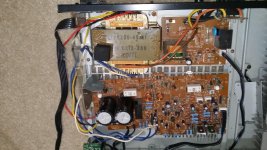
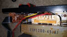
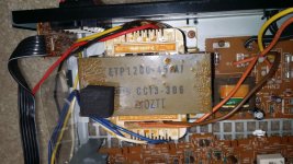
Open it up and take a few well-lit, in-focus photos of the connections near the AC and the transformer primary. If there is a multi-voltage capability, it may be easy to see.
Please have a look.
Attachments
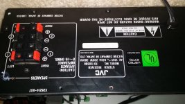
Sadly, it looks like a single primary.
No problem.
What would be the advatange of using a split supply vs dual supply? I am planning on using the +58V to drive the LM1875 using the single supply circuit provided. From the spec I see it can handle upto 60V. I am hoping I don't have to build a rail splitter.
Thanks.
It is likely that your transformer is a 40+40vac center tap, which would be rather typical for a decent retail discrete amplifier sold at a highly marketable 100+W per channel range of output power (which is just about the price/profit sweet spot).
Due to the photo I'd also think that it has a lower voltage tap for running a preamplifier or other accessories. A little more (careful) measuring could be informative. AC voltages between all of the lead wires may be a useful measure.
If I remember correctly, the 2 (sturdy) diode old fashioned, center tap specific, full wave rectifier (in the wikipedia) does *0.68, not *1.45. SO, 40vac*0.68 (2 sturdy diode full wave) is 27.2VDC!!! This is barely within range for LM1875 Turbo II (rigged for higher voltage and 8 ohm speakers or lighter load). To find out the voltage for sure, I think you'd have to build the center tap specific, 2 (sturdy) diode full wave bridge rectifier (followed by at least 4400uF per each rail), to proof it, first, before connecting your amplifier. My memory might not be accurate, and I have never tried that particular option. Got a couple sturdy diodes and some caps?
The above bit is indeed a guess.
It doesn't look suitable for a beginner project.
Simply put, fingernail size amp doesn't like huge size transformer--likely that the little chips will go kerblooie and smell very bad.
However, the following bit is not a guess.
Safer option for LM1875 and so much simpler, is to stop by at the radio shack for the 12+12vac 2a transformer, diy a simple power board, and run 2 channel 13W per channel LM1875 amplifier with the datasheet schematic (which does run well at that voltage, 17+17vdc) and the output power is 13W per channel (stereo) to most speakers (regardless of 4 ohm or 8 ohm load, according to datasheet charts. Bonus: highly linear for good tone--see the charts). So, if you were interested in a Straight-On-Spec build, that's the transformer you'd need for it, and that sort of build meets your specs for budget, preferred amplifier schematic and power output. At that (lower) voltage, both the linearity and longevity would be great.
So, I suggest to save the big transformer for a future project; and, simply use an economical and sensible transformer for your LM1875 project.
Last edited:
...stop by at the radio shack for the 12+12vac 2a transformer, diy a simple power board, and run 2 channel 13W per channel LM1875 amplifier with the datasheet schematic...
Rather an elegant solution, it seems to me. I happen to have some links handy.
25.2V CT 2.0A Heavy-Duty Chassis-Mount Transformer with Lead - Radioshack
RadioShack® 25.2V CT 450mA Std Chassis-Mount Xformer - Radioshack
Pre-Punched IC-Spacing Perfboard - Radioshack
RadioShack Perfboard Combo Pack (2-Pack) : Breadboards & IC sockets | RadioShack.com
.
Last edited:
What would be the advatange of using a split supply vs dual supply? I am planning on using the +58V to drive the LM1875 using the single supply circuit provided. From the spec I see it can handle upto 60V. I am hoping I don't have to build a rail splitter.
Dual (bipolar) power supplies have it, no contest. Starting with the fact that these chips are designed to work with dual supplies, so why go through a lot of contortions to do something else?
The contortions mainly have to do with needing more parts in the amplifier circuit. This means more crowding around the chip, where space is already limited. It also means just plain more parts. This is never desirable because it makes the amp circuit more complicated = more chances for error.
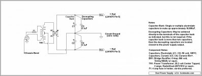
Still to me the question remains: why? It's not like dual supplies were complicated or expensive. They're neither, as I hope the below circuit shows.
You don't need rail splitters, or anything else that makes life complicated. Right now about 12 jillion amps are working happily and successfully with the circuit below. Voltage regulators? Some insist on them. Others, such as me, don't. Remember that well paid engineers have already done the heavy lifting for us. The result is that we can keep things simple, which is the point.
Your judgment rules, of course. Either way, just to mention it, bridge rectifiers come in a bewildering array of voltage and current specs, price apparently having little to do with what you get.
Multiply your local line voltage by 3-5 and use that for a voltage spec. Multiply the current you'll be drawing (in this case 2 amps) also by 3-5 and use that for a current spec. Any bridge rectifier that specs in this area will be fine, and higher is OK.
.
Attachments
Last edited:
It is likely that your transformer is a 40+40vac center tap, which would be rather typical for a decent retail discrete amplifier sold at a highly marketable 100+W per channel range of output power (which is just about the price/profit sweet spot).
Due to the photo I'd also think that it has a lower voltage tap for running a preamplifier or other accessories. A little more (careful) measuring could be informative. AC voltages between all of the lead wires may be a useful measure.
If I remember correctly, the 2 (sturdy) diode old fashioned, center tap specific, full wave rectifier (in the wikipedia) does *0.68, not *1.45. SO, 40vac*0.68 (2 sturdy diode full wave) is 27.2VDC!!! This is barely within range for LM1875 Turbo II (rigged for higher voltage and 8 ohm speakers or lighter load). To find out the voltage for sure, I think you'd have to build the center tap specific, 2 (sturdy) diode full wave bridge rectifier (followed by at least 4400uF per each rail), to proof it, first, before connecting your amplifier. My memory might not be accurate, and I have never tried that particular option. Got a couple sturdy diodes and some caps?
The above bit is indeed a guess.
It doesn't look suitable for a beginner project.
Simply put, fingernail size amp doesn't like huge size transformer--likely that the little chips will go kerblooie and smell very bad.
However, the following bit is not a guess.
Safer option for LM1875 and so much simpler, is to stop by at the radio shack for the 12+12vac 2a transformer, diy a simple power board, and run 2 channel 13W per channel LM1875 amplifier with the datasheet schematic (which does run well at that voltage, 17+17vdc) and the output power is 13W per channel (stereo) to most speakers (regardless of 4 ohm or 8 ohm load, according to datasheet charts. Bonus: highly linear for good tone--see the charts). So, if you were interested in a Straight-On-Spec build, that's the transformer you'd need for it, and that sort of build meets your specs for budget, preferred amplifier schematic and power output. At that (lower) voltage, both the linearity and longevity would be great.
So, I suggest to save the big transformer for a future project; and, simply use an economical and sensible transformer for your LM1875 project.
Yes you are right, there is a lower voltage of about 5V tap that is used to power the LED display and other things.
So I have be trying to figure out a simple approach to bring down the voltage - the transformer secondary is 42V and dc from the caps is 58V. The caps are old but rated at 8300uf/63V I think.
I agree the easiest option is to buy the transformer and build a rectifier, fairly straight forward. But hey, who wants straight forward
") . No seriously - the main reason is safety. I thought that if I could use the PSU from the old receiver, I would not have to mess around with the AC, which I am not too familiar. As a bonus it has a power on switch, a couple of relays that seem to work to discharge the 2 63V caps and also cut of power to the big transformer. For the folks using it, it may be better.
. No seriously - the main reason is safety. I thought that if I could use the PSU from the old receiver, I would not have to mess around with the AC, which I am not too familiar. As a bonus it has a power on switch, a couple of relays that seem to work to discharge the 2 63V caps and also cut of power to the big transformer. For the folks using it, it may be better.
Last edited:
Dual (bipolar) power supplies have it, no contest. Starting with the fact that these chips are designed to work with dual supplies, so why go through a lot of contortions to do something else?
The contortions mainly have to do with needing more parts in the amplifier circuit. This means more crowding around the chip, where space is already limited. It also means just plain more parts. This is never desirable because it makes the amp circuit more complicated = more chances for error.
Still to me the question remains: why? It's not like dual supplies were complicated or expensive. They're neither, as I hope the below circuit shows.
You don't need rail splitters, or anything else that makes life complicated. Right now about 12 jillion amps are working happily and successfully with the circuit below. Voltage regulators? Some insist on them. Others, such as me, don't. Remember that well paid engineers have already done the heavy lifting for us. The result is that we can keep things simple, which is the point.
Your judgment rules, of course. Either way, just to mention it, bridge rectifiers come in a bewildering array of voltage and current specs, price apparently having little to do with what you get.
Multiply your local line voltage by 3-5 and use that for a voltage spec. Multiply the current you'll be drawing (in this case 2 amps) also by 3-5 and use that for a current spec. Any bridge rectifier that specs in this area will be fine, and higher is OK.
.
Thanks.
It was exactly to avoid the contortions that I wanted to use as is the 58V dc that is available in the receiver, but I see it may not be the optimal voltage for the chip.
So my current thought is to use a LM317 with a MJE3055T transistor for higher current. Still I am planning to use a single supply. If I find LM337 then may be I can build the rail splitter and go with the dual supply circuit.
Last edited:
I have not heard that Any differential input device such as an OpAmp or Integrated Amplifier chip has been Designed for Dual supply use. The device can not tell if it is supplied by a Single or Dual supply voltage. In fact the Capacitor decoupled output has some advantages in requiring no Protective circuits for the Speaker. We all know this ?
What amp circuit gives least distortion for about 10W + 10W.
Thanks
Be careful buying low power amplifiers.
They tend not to have the dynamic range needed for good clear sound.
When I started designing amplifiers I started with low voltage power rails and found the amplifier distorted quite soon in the volume range. The transients were being clipped.
I moved on to 45V+ rails and that improved matters a lot.
So are you saying that using high voltage is good. I am getting conflicting thoughts on this - some say don't drive LM1875 more than 40V, I was hoping to use my current PSU supply of 58V directly since the spec says it can handle max of 60V. I know I will need a huge heat sink, I have one, it was handling the output transistors for 280W.
So are you saying that using high voltage is good..
I was speaking of amplifiers in general.
I would look at 40 volts minimum.
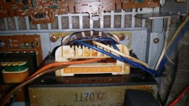
It would be really great if you'd measure the transformer and find out
What does the 3 wires on one side do (AC measures across and between)?
What does the 3 wires on the other side do (AC measures across and between)?
What does the 2 wires in the middle do (AC measure)?
And, then probably sketch that out and post it, with the measures.
I think that if it is a standard model, you're going to find:
40,0,40vac (power amp)
15,0,15vac (accessory circuit)
120vac (the primary, input)
If that is the case, then simply Don't use the 40,0,40vac wires.
The accessory circuit, typically either 12,0,12vac or 15,0,15vac can run the power supply and your lm1875's.
It would be really great if you'd measure the transformer and find out
What does the 3 wires on one side do (AC measures across and between)?
What does the 3 wires on the other side do (AC measures across and between)?
What does the 2 wires in the middle do (AC measure)?
And, then probably sketch that out and post it, with the measures.
I think that if it is a standard model, you're going to find:
40,0,40vac (power amp)
15,0,15vac (accessory circuit)
120vac (the primary, input)
If that is the case, then simply Don't use the 40,0,40vac wires.
The accessory circuit, typically either 12,0,12vac or 15,0,15vac can run the power supply and your lm1875's.
OK,
the transformer is wired kind of weirdly:
The brown and orange wires are primary : 110V
The 2 blue and white secondary: 3.9V dual
The red, black and yellow wires: 43V dual
SO I guess out of luck on the 12/15v idea
.
Oh me & oh my. I greatly respect your intention to mess around with the thing, it is, after all, what these forums are for. And I really hate to be a wet blanket...but...
The spec for the rail splitter is 20ma out. It's for preamps and mixers and such, not nearly enough for, for instance, a 20 watt amp.
(watts = volts x amps = VA)
The LM317 or similar would certainly drop 58 volts to, say, 30 volts. Though better might be the LM150 with its 3 amp output (whichever you use, heat sink it!). So sure, single supply, why not.
Do be aware that 58 volts might or might not knock you across the room, but it sure can give you a serious tingle...or worse. Be safe, unplug.
.
30vdc each rail? Nope. Well the thing is that TI's headline says 20W amp and their datasheet graph says 22V for that.
I'd hazard to say, that *conditionally* it is a 22W amp and 26v is okay.
Therefore, I think it can do a bit more than the manufacturer claims.
But if you think it can do even more than that, then I'm at least very curious; because, in that case, my drink wasn't nearly as good as yours.
However, higher voltage and using a fruit size transformer for a fingernail size chip doesn't work.
I tested that far too many times. That combination breaks and there's no exceptions. However, it does sometimes take a portion of a year and sometimes the breakage is mild rather than spectacular. A long time ago, I had made it through a nifty project for about half a year and then. . . there was some egg on face and some re-design to do. Seven years later and considerable number of re-designs, the stuff works even better for audio quality and doesn't break. However, every time I see a too-big transformer with an LM1875, I have a rather bad feeling because that usually goes badly. I actually don't know why anyone thinks a transformer so far bigger than the chip capacity is a good idea, but online lore supports it although the facts and track record certainly don't. That bit of online lore is just a recipe for either a little smoke or really bad linearity or both. I've just got to say that a far too big transformer in combination with a little chip is not a good use of your time and so I think you should try something else, preferably more productive.
Last edited:
Given my track record of hot-rodding and overbuilding anything, if I'm trying to do the opposite and saying your power is too much, well, I think that ought to at least cause you a curiosity. Meanwhile, I'd like to again mention purchasing a more suitable transformer for your LM1875 amplifier.
It is true that you would probably succeed in powering the amp with the overly large transformer that you have and it is true that the amplifier may work for a portion of a year before breaking down from the strain. I just think that we should probably want to do a little better than that so that you can enjoy it for a longer time.
It is true that you would probably succeed in powering the amp with the overly large transformer that you have and it is true that the amplifier may work for a portion of a year before breaking down from the strain. I just think that we should probably want to do a little better than that so that you can enjoy it for a longer time.
Hi,
thanks for sharing your experience and knowledge.
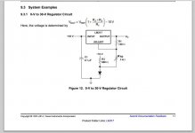
Before I give up on my idea, I would like your opinions on this option. From LM317 spec sheet there is this attached circuit.
I see various place in my old PSU circuit that has a potential of -12V/-24V with respect to ground. I don't know how much current they can supply hence won't be able to use that directly but I am fairly certain it can supply 75mA. Thus with the attached circuit I am hoping I can bring down the regulated output to about 44V by using the following values for R1=400, R2=3K and R3=15K. The input voltages would be 58V on the top and -12V on the one attached to R3. This way I can bring down the voltage to optimal values for LM1875 and still use the PSU.
Also I will have to use the diode with transitor for high current from LM317, I have done this before works well for LM3886 amp which runs from walwarts, through dc dc boost coverter, LM317, transistor for high current and a LC low pass. BTW I was persuaded not to run from the walwarts especially since I had to create virtual ground and it is all too noisy for clean sound. Yesterday I was at Frys and when I lifted one of the $350 receivers, it was super light and I peeked in to see no transformer. I am sure they are using SMPS inside.
Also single vs dual, like someone mentioned on the thread it won't be visible to the chip, all it sees is potential difference.
Also the idea is to learn so a little experimentation is in order.
Thanks.
thanks for sharing your experience and knowledge.
Before I give up on my idea, I would like your opinions on this option. From LM317 spec sheet there is this attached circuit.
I see various place in my old PSU circuit that has a potential of -12V/-24V with respect to ground. I don't know how much current they can supply hence won't be able to use that directly but I am fairly certain it can supply 75mA. Thus with the attached circuit I am hoping I can bring down the regulated output to about 44V by using the following values for R1=400, R2=3K and R3=15K. The input voltages would be 58V on the top and -12V on the one attached to R3. This way I can bring down the voltage to optimal values for LM1875 and still use the PSU.
Also I will have to use the diode with transitor for high current from LM317, I have done this before works well for LM3886 amp which runs from walwarts, through dc dc boost coverter, LM317, transistor for high current and a LC low pass. BTW I was persuaded not to run from the walwarts especially since I had to create virtual ground and it is all too noisy for clean sound. Yesterday I was at Frys and when I lifted one of the $350 receivers, it was super light and I peeked in to see no transformer. I am sure they are using SMPS inside.
Also single vs dual, like someone mentioned on the thread it won't be visible to the chip, all it sees is potential difference.
Also the idea is to learn so a little experimentation is in order.
Thanks.
Attachments
Last edited:
- Status
- This old topic is closed. If you want to reopen this topic, contact a moderator using the "Report Post" button.
- Home
- Amplifiers
- Chip Amps
- Which amp for least distortation (10W + 10W) under $50. No class D please.