So I am building a PSU for my preamp that will 48v and dual 15v supply. I want the power to be easily available so I decided to run the PSU in 9V DC input.
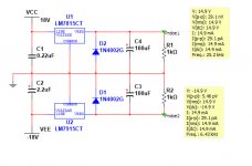
Here is what I am doing. A 9V is stepped up into 48v. It then spited into dual 24v and Regulated by 78L15 and 79L15 to get a dual 15v. I am using a XL6009 module and successfully obtained 48v and dual 24v. Everything work as expected until the last voltage regulating stage. I never got the 78L15 and 79L15 function properly. Here is the schematic of my circuit.
The green circuit is working as expected while THE red circled part is not. I am sure my 78L15 and 79L15 are good I have tested them individually. They just don't work when combining the boost converter and the bipolar supply. Can some please suggest a possible explanation to this?
Here is what I am doing. A 9V is stepped up into 48v. It then spited into dual 24v and Regulated by 78L15 and 79L15 to get a dual 15v. I am using a XL6009 module and successfully obtained 48v and dual 24v. Everything work as expected until the last voltage regulating stage. I never got the 78L15 and 79L15 function properly. Here is the schematic of my circuit.
An externally hosted image should be here but it was not working when we last tested it.
The green circuit is working as expected while THE red circled part is not. I am sure my 78L15 and 79L15 are good I have tested them individually. They just don't work when combining the boost converter and the bipolar supply. Can some please suggest a possible explanation to this?
Possible cause is the centre voltage or 0v point. It is floating. If you use two 7815's in series, that may work.
Thanks for your help. I am not a expert on electronic. What do you mean by floating? How to connect two 7815's in series and should I do the same thing with 7915?
You can't use the regulators like that. Either use another SMPS to generate negative rail, or use a supply splitter.
That regulators circuit is taken from the internet and I think it is pretty common for this connection. I just replaced the input source. And I also added a supply splitter into my circuit (the second stage).
The regulators are not the problem, it is your floating 0V.
Sorry I don't understand the term floating 0V. Can you explain more on this? Thanks
The input supply has a ground referenced to 0V. (Node connected to GND).
The 0V reference to the two regulators is being split by two 10k resistors.
When you connect the two circuits together, the lower resistor is effectively removed from the circuit by the two 'grounds'.
By itself the circuit would work but the current available would be very small, limited by the current available through the 10k resistors. In that sense it is NOT 'dual' 24V, but a single 48V with a virtual ground formed by the potential divider of 10k+10k.
What will not work is the interconnection of the two downstream circuits.
The maximum current will be limited to 2.4mA. If you want more current you will have to use a virtual ground generator, but cannot then connect a microphone to the input of the circuit as you will damage this generator.
I would advise generating one 30V rail and using single-supply applications if possible.
The input supply has a ground referenced to 0V. (Node connected to GND).
The 0V reference to the two regulators is being split by two 10k resistors.
When you connect the two circuits together, the lower resistor is effectively removed from the circuit by the two 'grounds'.
By itself the circuit would work but the current available would be very small, limited by the current available through the 10k resistors. In that sense it is NOT 'dual' 24V, but a single 48V with a virtual ground formed by the potential divider of 10k+10k.
What will not work is the interconnection of the two downstream circuits.
The maximum current will be limited to 2.4mA. If you want more current you will have to use a virtual ground generator, but cannot then connect a microphone to the input of the circuit as you will damage this generator.
I would advise generating one 30V rail and using single-supply applications if possible.
Is it mean that there will be no proper way to generate bipolar supply from DC ?
See this article on virtual grounds -- you can use BUF634 or LME49600:
Virtual Ground Circuits
Virtual Ground Circuits
The input supply has a ground referenced to 0V. (Node connected to GND).
The 0V reference to the two regulators is being split by two 10k resistors.
When you connect the two circuits together, the lower resistor is effectively removed from the circuit by the two 'grounds'.
By itself the circuit would work but the current available would be very small, limited by the current available through the 10k resistors. In that sense it is NOT 'dual' 24V, but a single 48V with a virtual ground formed by the potential divider of 10k+10k.
What will not work is the interconnection of the two downstream circuits.
The maximum current will be limited to 2.4mA. If you want more current you will have to use a virtual ground generator, but cannot then connect a microphone to the input of the circuit as you will damage this generator.
I would advise generating one 30V rail and using single-supply applications if possible.
I finally get them working. The problem is I test the 7815 and 7915 one by one. When I hook them up at the same time they work. A precise +15v and -15v.
I test the supply on my preamp and everything is working. However I find that the preamp will distort when the output hit around -2db. Usually I won't record the vocal at this level but I don't think distortion is normal. Is it relate to the psu I use? Or due to the current issue you have mentioned?
Could very well be either or both. If you are able to capture -10dB without distortion it is fine. However if it is audible at -2dB it will be present in your recording at -35dB also as THD becomes audible only when it crosses a few percentage points - 1 or 2%. The goal is to get THD below -60dB while recording, which means you need to have a clean signal till clip point and on the analog out, till at least +13dBu.
In any case, have you tried to connect a microphone with phantom power to the circuit? Does it work?
In any case, have you tried to connect a microphone with phantom power to the circuit? Does it work?
However if it is audible at -2dB it will be present in your recording at -35dB also as THD becomes audible only when it crosses a few percentage points - 1 or 2%. The goal is to get THD below -60dB while recording, which means you need to have a clean signal till clip point and on the analog out, till at least +13dBu.
This part is too professional for me to understandng. What do you mean by THD?
In any case, have you tried to connect a microphone with phantom power to the circuit? Does it work?
I have try out the phantom power yet but I later on find that the 48v will actually become 24v as the GND point is changed.
Today I tried a different approach on make a dual supply. I try to use 2 XL6009 module and connect 1st +out the 2nd -out to represent the GND, reamaining +/- pad of each module as the +15v and -15v. However there is no output immediately when I connect two module. Why is that?
Hi
When you are able to hear distortion (THD = Total Harmonic Distortion), it means distortion is about 1 to 2% of the overall output.
However when recording we need to keep distortion really low, to be able to faithfully capture the performance.
A target of 0.05% is reasonable. This is about -66dB. You can calculate this here: THD to dB - convert percent % to decibels dB percentage voltage % vs per cent converter THD+N total harmonic distortions calculation signal distortion factor attenuation in dB to distortion factor k in percent decibel damping - sengpielaudio Sengpiel
The problem is that if your have audible distortion and assuming it's about 2%, distortion will be around -35dB which is too high at that level.
Basically, most of what you record will not sound good. For a recording made at -10dB for example, your distortion level will be at best -45dB. Which is not very nice.
Also when you mix multiple tracks made at such high levels of distortion, the nonlinear products will add up, making it sound worse and worse.
I don't know what kind of recording you are planning. IF this is outdoor noisy environment you might be okay. But for any kind of music work, this setup will not work out very well.
You cannot use phantom power with this circuit, as you have found. Even using two supplies will not work as the battery ground is still connected to mic ground for phantom power, yet the same ground must connect somewhere else for the signal.
At the minimum, you will need two batteries or the second supply must also isolate the ground totally from the phantom power circuit.
Wow that is really useful information. Thanks for that.
Hi
I don't know what kind of recording you are planning. IF this is outdoor noisy environment you might be okay. But for any kind of music work, this setup will not work out very well.
Yes I am use the preamp for music purpose. It is not for publishing but I still want to get the quality as good as possible.
Hi
You cannot use phantom power with this circuit, as you have found. Even using two supplies will not work as the battery ground is still connected to mic ground for phantom power, yet the same ground must connect somewhere else for the signal.
I am total confused here. I am just making a PSU for the Phantom Power. Isn't that I just need a +48v in order to make it work? Do you mean that the battery ground must be isolated with the mic ground?
Anyway this is the preamp I have built:

Last edited:
Hi
Pin 1 of the XLR connects to signal ground.
+48V is between this 'ground' and the mic input (pin 2+3 of XLR). I am assuming you will try and get this 48V from the output of the generator and the battery negative terminal.
Your INA217 and OPA137 also need to refer their + and - supplies to a ground, as drawn.
The problem is that in your power supply you are routing both these grounds separately, but in this schematic they are to be joined together.
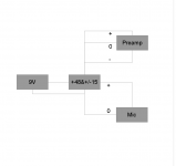
Are you able to visualise the problem? You have generated a virtual ground using your potential divider, but are now trying to connect it back to the negative terminal of the battery. In the attached flowchart, you CANNOT connect the two 0V points together, yet your schematic requires it. I have only drawn the power supply routing, not the signal.
You need two different batteries and two different power supplies to do what you are trying to do, or run both off a virtual ground system.
For example, you can use one generator to create +40V and split it into +/-15V, and use another generator to take that +15V and step it up to +48V for the mic. The key point is that the ground reference for the microphone phantom power and for the signal circuitry must be the exact same node.
Now to your rail splitter, better use a circuit that can supply at least 50-60mA if you want a clean sound. There are plenty of virtual ground circuits used in the headphone amp world, for example, that should do this just fine.
Pin 1 of the XLR connects to signal ground.
+48V is between this 'ground' and the mic input (pin 2+3 of XLR). I am assuming you will try and get this 48V from the output of the generator and the battery negative terminal.
Your INA217 and OPA137 also need to refer their + and - supplies to a ground, as drawn.
The problem is that in your power supply you are routing both these grounds separately, but in this schematic they are to be joined together.
Are you able to visualise the problem? You have generated a virtual ground using your potential divider, but are now trying to connect it back to the negative terminal of the battery. In the attached flowchart, you CANNOT connect the two 0V points together, yet your schematic requires it. I have only drawn the power supply routing, not the signal.
You need two different batteries and two different power supplies to do what you are trying to do, or run both off a virtual ground system.
For example, you can use one generator to create +40V and split it into +/-15V, and use another generator to take that +15V and step it up to +48V for the mic. The key point is that the ground reference for the microphone phantom power and for the signal circuitry must be the exact same node.
Now to your rail splitter, better use a circuit that can supply at least 50-60mA if you want a clean sound. There are plenty of virtual ground circuits used in the headphone amp world, for example, that should do this just fine.
Attachments
Are you able to visualise the problem? You have generated a virtual ground using your potential divider, but are now trying to connect it back to the negative terminal of the battery. In the attached flowchart, you CANNOT connect the two 0V points together, yet your schematic requires it. I have only drawn the power supply routing, not the signal.
I understand what you mean now. I later on find that it is not working as the 48v will actually become 24v if virtual GND is used. I think using another XL6009 module with virtual GND as input GND will solve the problem. But the current will be big consideration.
Anyway I have another approach now.
An externally hosted image should be here but it was not working when we last tested it.
I am trying to use LT1054 to create a bipolar supply. And using XL6009 for phantom power supply. This circuit do not involve a virtual Ground and so the problem you mention will not exist. Can you please give a common on this?
- Status
- This old topic is closed. If you want to reopen this topic, contact a moderator using the "Report Post" button.
- Home
- Amplifiers
- Chip Amps
- Unknown 78l15 Regulator problem. Very Weird ????