Hello! ")
As I already mentioned in my introduction I´m currently building a 4.1 sound system which will mainly consists of four Dayton RS100-4 (from Klangriese by Udo Wohlgemuth), a Mivoc XAW 210 HC (Micro Cube by Hobby-Hifi) and two LM1876 for amplification. I already did a test with two speakers and the subwoofer with my SymAsym and it sounded really nice although the Micro Cube struggled to adapt with the room at the beginning.
At the moment I´m designing the layout for the chips. This is what I´ve came up with so far (stand-by parts not implemented yet!):


Now I´m very uncertain whether the grounding is good the way I routed it. I read a lot of articles in this forum about this topic lately but still there are very different types of solutions on how to achieve a clean ground wiring/routing. It´s irritating! Some suggest to use ground-planes, others star-grounding and even others T-shapes (like I did it in my version).
So this raises a big question for me: What is the best way to do ground routing?
Regards,
Martin
As I already mentioned in my introduction I´m currently building a 4.1 sound system which will mainly consists of four Dayton RS100-4 (from Klangriese by Udo Wohlgemuth), a Mivoc XAW 210 HC (Micro Cube by Hobby-Hifi) and two LM1876 for amplification. I already did a test with two speakers and the subwoofer with my SymAsym and it sounded really nice although the Micro Cube struggled to adapt with the room at the beginning.
At the moment I´m designing the layout for the chips. This is what I´ve came up with so far (stand-by parts not implemented yet!):
Now I´m very uncertain whether the grounding is good the way I routed it. I read a lot of articles in this forum about this topic lately but still there are very different types of solutions on how to achieve a clean ground wiring/routing. It´s irritating! Some suggest to use ground-planes, others star-grounding and even others T-shapes (like I did it in my version).
So this raises a big question for me: What is the best way to do ground routing?
Regards,
Martin
You can get into various grounding schemes, but one thing that is very important is to not have noise grounds (like input and feedback loop grounds) going through the same trace back to the ripple capacitor as the power grounds and bypass grounds. It looks like your layout could benefit from even minor layout changes.
Some kind of star grounding is a good idea. Just group the grounds together following the above principles.
Here's an in-depth article that might help you. Grounding Principles - The Signal - Archives - TI E2E Community
Some kind of star grounding is a good idea. Just group the grounds together following the above principles.
Here's an in-depth article that might help you. Grounding Principles - The Signal - Archives - TI E2E Community
Thank you for the article! It is really well written and understandable.
I think I will go with a star grounding scheme with two star points. One for signal ground and one for power ground. Signal ground will then be connected at one single point to power ground and from there to the mains PE. Is this one possible way to do it?

Could you elaborate more what these minor layout changes would look like? (maybe a small drawing or something...)
I think I will go with a star grounding scheme with two star points. One for signal ground and one for power ground. Signal ground will then be connected at one single point to power ground and from there to the mains PE. Is this one possible way to do it?
Could you elaborate more what these minor layout changes would look like? (maybe a small drawing or something...)
.
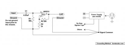
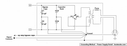
Below is my understanding of the right way to do it. It's based on the reference posted by Fast Eddie D, and on some circuits by D. Self. The NE5532 is arbitrary, it's there so a complete circuit will be illustrated.
On another subject, I don't think you want to include R16. As drawn it carries the full output of the amplifier, and will have to be 20 watts or whatever.
A related but different subject, in the first circuit you posted I'm guessing R15 and C13 are a zobal network (Boucherot cell). Zobals are intended to react between the speaker and amp, so this should be on the other side of R16 (if present). As it's drawn now the zobal sees the 10 ohms of R16 as part of the speaker, which can confuse things.
Zobals are actually something of a design exercise, not at all trifling, and can do more harm than good when wrongly applied. Just lifting values from another circuit might or might not give the desired result. Key fact: the engineers who designed the LM1875 in the first place include zobals in other suggested circuits, but not the one you're using.
.
Attachments
Last edited:
Sorry for the confusion. To clear things up:
It seems fine by me to connect things like Speedskater described it above. But how will this look like if I have a chassis which mostly consists of insulating materials (like plastic or wood) and only have a aluminium shield at the rear and the front of my chassis? Do I connect both aluminium parts with a wire, leave it completely disconnected or maybe do something completely different?
- it´s a LM1876 (not LM1875!)
- I´m using a symmetrical power-supply
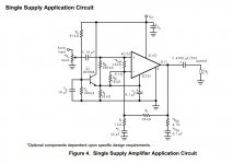
- R16 (10 Ohm) will have a small inductance paralleled, like it is shown in figure 4 in the datasheet
- R16 shouldn´t have to carry that much current since the inductance will do so for the most part
- the schematic is exactly the same (except for the standby part) as the one in the datasheet (figure 4 again)
It seems fine by me to connect things like Speedskater described it above. But how will this look like if I have a chassis which mostly consists of insulating materials (like plastic or wood) and only have a aluminium shield at the rear and the front of my chassis? Do I connect both aluminium parts with a wire, leave it completely disconnected or maybe do something completely different?
.
<< it´s a LM1876 (not LM1875!) >>
Yep. Typo by me.
<< the schematic is exactly the same (except for the standby part) as the one in the datasheet (figure 4 again) >>
This seems to need clearing up because there must be different versions or different data sheets. Mine is Texas Instruments, "SNAS097C – MAY 1999 – REVISED APRIL 2013"
Below is the figure 4 that I see. Or you meant figure 5, another typo? These foreign keyboards they sell us are really worthless.
Attachments
Last edited:
.
<< I have a chassis which mostly consists of insulating materials (like plastic or wood) and only have a aluminium shield at the rear and the front of my chassis? Do I connect both aluminium parts with a wire, leave it completely disconnected or maybe do something completely different? >>
You're kinda-sorta taking your chances by not having your circuit in a shielding enclosure--meaning a grounded metal enclosure. Studio and performing environments are the worst for radio frequency noise, but anywhere near computers is bad too, and in fact rf noise is everywhere these days, and can cause strange problems in unshielded circuits.
In any case yes, the correct procedure is to connect any/all metal shielding plates together, and connect them to the ground point, which is actually the third prong of the power cord. Thus rf noise is shunted to ground. "Ground" really does mean ground because the third prong of the power cord is ultimately connected to a 10-foot metal rod driven into the earth near your electric meter. All electrical power installations are done this way, worldwide (with variations according to local codes).
As a matter of interest, a metal housing shields against rf noise because rf energy induces microcurrents in the housing, the same thing that happens on a much larger scale in a transformer. The rf energy is absorbed by this (so to speak), and the microcurrents are conducted to ground.
These microcurrents are the reason for not using a metal housing for an input signal ground. At any given time a metal housing is simply a mess of tiny little local voltages and currents appearing and disappearing. These are too small to affect the much larger power supply, but they can distort the small audio signal.
"Distortion" is relative, of course. The various voltages and currents are simply combining according to the laws laid down by Ma Nature. But as far as we're concerned it's distortion and we want to avoid it.
.
Last edited:
Well figure 4 was referred to the datasheet from National Semiconductor which I linked to, if you´d just followed the link. In the Texas Instruments datasheet it´s figure 5.
I am aware of the lack of shielding against noise in a non-metal case. The reason for not using a metal case is simply that I don´t want to spend that much money. Appropriate ones like the Hifi2000/Galaxy series starts at about 50€ going easily up to over 100€ which is too much for a student like me. If you know any good looking and relatively cheap chassis let me know of course!
I am aware of the lack of shielding against noise in a non-metal case. The reason for not using a metal case is simply that I don´t want to spend that much money. Appropriate ones like the Hifi2000/Galaxy series starts at about 50€ going easily up to over 100€ which is too much for a student like me. If you know any good looking and relatively cheap chassis let me know of course!
Could you elaborate more what these minor layout changes would look like? (maybe a small drawing or something...)
What I do is plan my layout with the star ground approximately in the middle of the board, and then estimate what circuits go where. Then I start drawing my layout.
Remember that any star ground must be bypassed with an appropriate capacitor. In the case of your chip amp, this capacitor must be a large electrolytic. You could do an electrolytic array if you want, and you can bypass it with a film cap too if you'd like.
Remember that cascaded star grounds (like you show) can cause noise and nonlinearities if not done carefully and sparingly.
I did a quick and dirty test whether I could make it with a single star:

Not working out very well... there are still traces left and most of them are too long. Star-grounding chip amps is not an easy task. Discrete amplifiers have more freedom regarding that aspect. I would try it with a nested star like I´ve drawn it before. Though maybe you have any further ideas? I really wonder whether there isn´t already a good layout for the LM1876...
Not working out very well... there are still traces left and most of them are too long. Star-grounding chip amps is not an easy task. Discrete amplifiers have more freedom regarding that aspect. I would try it with a nested star like I´ve drawn it before. Though maybe you have any further ideas? I really wonder whether there isn´t already a good layout for the LM1876...
Updated version with rounded traces and two more capacitors (4 x 3300µF in total now):

About bypass capacitors: I placed two near the left of the chip (C35, C36) but didn´t include any at the big electrolytic ones (at the star point). You said that I should place bypass capacitor there though, right?
I still want to use the stand-by function. In my current schematic it has a 100k resistor in series to V+ (see the first post for the schematic!). Now, does this work? I´m unsure because the datasheet doesn´t explicitly state how it should be connected. It only says that it activates stand-by mode when there is a potential of 2.5 - 5V.
Also I wonder what I should do with the mute pins. I do not need them. Can I leave them disconnected? Or do they need a specific potential (like 0V at ground)?
I searched for some chassis again and found this: Botier DIY aluminium Noir panneau perfor 215x308x70mm - Audiophonics I can still afford this and it looks like it has a decent quality. The size might fit but is tight as I need 4 channels (which means 2 x LM1876 boards).
Finally I got some work done on this project. The layout is pretty much finished, the chip is being tested right now and I will probably order some PCBs soon.
The sound is incredibly good for such a small chip. Of course, compared with a SymAsym it does not perform better, especially the highs are not as precise and the overall less power is slightly noticeable. Still, the LM1876 was definitely the right choice building a multichannel setup.
What really made me happy though is that there is just no grounding hum/noise. I used the methods described before in this thread. A big "Thank you!" to the people helping me with this issue.
The layout:

Component arrangement inside the chassis:

OSHPark PCB preview:


The sound is incredibly good for such a small chip. Of course, compared with a SymAsym it does not perform better, especially the highs are not as precise and the overall less power is slightly noticeable. Still, the LM1876 was definitely the right choice building a multichannel setup.
What really made me happy though is that there is just no grounding hum/noise. I used the methods described before in this thread. A big "Thank you!" to the people helping me with this issue.
The layout:
Component arrangement inside the chassis:
OSHPark PCB preview:
- Status
- This old topic is closed. If you want to reopen this topic, contact a moderator using the "Report Post" button.
- Home
- Amplifiers
- Chip Amps
- BrambleAmp - LM1876 Gainclone