I also have another schematic for a finished non-inv amp for the LM3886, from Elektor. In that schematic, they've handled the mute pin too, so one can simply pick up the resistor values based on what they've put in it. (They've put in the option for a mute switch, which I don't intend to use.... I'll just keep the circuit permanently "un-muted" when I design the PCB.)
I have this article in PDF format, in case you want me to mail it to you. It's a one-page thing with schematic and PCB layout.
I have this article in PDF format, in case you want me to mail it to you. It's a one-page thing with schematic and PCB layout.
You're right! I'll have to make R2 into 1K, and probably make C2 to 47uF to compensate and keep the same roll-off frequency.theChris said:the circuit as shown has a gain of about 3. it needs to be boosted by a bit.
The two resistors in parallel are because some people on the chip amps forum say that a higher power rating for the feedback resistor seems to improve the sound a bit. I thought this would be a good way to reach the 0.5W rating using two 0.25W MFR.why 2 42k resistors in parallel. also the input capacitor may now be needed.
And can you please explain the comment about the input cap? You think it may now be needed? I already have one.
Hi Tarun
I don't get how increasing the power rating of the f/b resistors can improve the sound. Anyway, electrically it should be the same. Some may say that heating effects in smaller resistors can raise the temperature enough to change the resistor value, leading to distortion. Could be, but IMO, the effect won't be audible except to the golden eared. Esp. if you're using metal film, which has a good tempco.
Please verify (using SPICE and an ordinary opamp model in place of the 3875) the effect of the 50pF cap in the feedback loop. Or else some simple math will tell you the 3dB point of the ckt (no, I'm recovering from flu, and you can't tempt me even with an Uncle Harry knob to do the math for you!") ). If there's a rolloff of more than 1dB in the audio band, it's gonna be a lot more apparent than the effect of resistor heating.
). If there's a rolloff of more than 1dB in the audio band, it's gonna be a lot more apparent than the effect of resistor heating.
On splitting the grounds apart, you could do the following: drill many holes on the PCB along the edge where the ground planes are split. You can solder short bits of wire across these, which you can later clip off if the hum gets annoying. You can also use a 50 - 100 ohm resistor here, because in case the input connection to the amp is removed (remember Murphy's law: sh*t happens!), you can say goodbye to whatever load is connected. The resistor will provide an "emergency" ground connection. In normal use (when there is an input), the ground return path will have a lower impedance than the resistor, so it shouldn't matter.
Madhu, welcome to DIYAudio. Using a supply of 35 volts with this chip is a bit risky. I once blew out a pair of 3886s when I used a 30-0-30 trafo. Of course, no-load DC is 42V here, but under load it should be lower than the chip's rating. Well, I guess turn-on transients did the 3886s in. Using a 25-0-25 (to get a nominal of 32V) is probably a safer idea. Cin of 10uF means using an electrolytic (err... BAD!) or a Z5U ceramic (also bad). You probably wont need LF response to go down to 0.72 Hz anyway. Use a 1uF film capacitor (get them at Cee Pee electronics. Ask for "box type" capacitors, he'll know). Perhaps you can use two of them in parallel.
I don't get how increasing the power rating of the f/b resistors can improve the sound. Anyway, electrically it should be the same. Some may say that heating effects in smaller resistors can raise the temperature enough to change the resistor value, leading to distortion. Could be, but IMO, the effect won't be audible except to the golden eared. Esp. if you're using metal film, which has a good tempco.
Please verify (using SPICE and an ordinary opamp model in place of the 3875) the effect of the 50pF cap in the feedback loop. Or else some simple math will tell you the 3dB point of the ckt (no, I'm recovering from flu, and you can't tempt me even with an Uncle Harry knob to do the math for you!
). If there's a rolloff of more than 1dB in the audio band, it's gonna be a lot more apparent than the effect of resistor heating.On splitting the grounds apart, you could do the following: drill many holes on the PCB along the edge where the ground planes are split. You can solder short bits of wire across these, which you can later clip off if the hum gets annoying. You can also use a 50 - 100 ohm resistor here, because in case the input connection to the amp is removed (remember Murphy's law: sh*t happens!), you can say goodbye to whatever load is connected. The resistor will provide an "emergency" ground connection. In normal use (when there is an input), the ground return path will have a lower impedance than the resistor, so it shouldn't matter.
Madhu, welcome to DIYAudio. Using a supply of 35 volts with this chip is a bit risky. I once blew out a pair of 3886s when I used a 30-0-30 trafo. Of course, no-load DC is 42V here, but under load it should be lower than the chip's rating. Well, I guess turn-on transients did the 3886s in. Using a 25-0-25 (to get a nominal of 32V) is probably a safer idea. Cin of 10uF means using an electrolytic (err... BAD!) or a Z5U ceramic (also bad). You probably wont need LF response to go down to 0.72 Hz anyway. Use a 1uF film capacitor (get them at Cee Pee electronics. Ask for "box type" capacitors, he'll know). Perhaps you can use two of them in parallel.
Looks like Tarun already did the math... Maybe I should read a bit more before I post? 
One more thing: you mentioned high tech diodes. These are probably Schottky or fast recovery types. I can't get why they're used in an audio amp supply. They're meant for switchers. In a linear supply, their fast turnoff will inject harmonics of 50 Hz into the power lines, which if not adequately filtered, can cause problems. Look at the PSU to any low-noise measurement equipment from a quality firm, for instance an HP spectrum analyzer. The psu diodes will have capacitors across them (these must be able to withstand the AC voltage being applied) to slow down the diode switching. Thus, turn-off transients (which can sometimes go up to several megahertz!) are avoided at the source. The downside to all this is power loss in the diodes... small price to pay IMO.
Aside: ultra-fast switching diodes (backward diodes, some schottkys, etc) are sometimes used as "harmonic generators" to multiply the frequency of an RF signal. Introduce switching harmonics, then filter out the one you need.
I am a little confused.
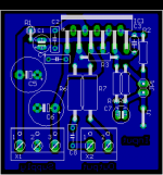
Output connection X2-1 and X2-2. If the load (speaker) goes between these 2 points, you will not get any potential. Your speaker will see the equivelant of a 12.7 ohm resistor in series with a 100nF cap accorss it's terminals. The amp output just flapping in the wind, with no path to ground.
Maybe there is supposed to be a ground/common connection between the C8 and terminal point X2-1?
A quick look at your PCB seems to refelct what I think is an error in the schematic.
Aud_Mot
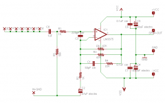
See the schematic here, taken from a common Gainclone reference source, the Decibel Dungeon. The author uses two feedback resistors in parallel. I agree with you 100% that electrically, a higher-wattage resistor will not have an audible effect, but I decided to make provisions for it on the PCB (hence the schematic) anyway, in case someone sometime wants to use my PCB to experiment with high-wattage. And if ears could be categorised, I'm probably steel-eared rather than golden.roadkill said:I don't get how increasing the power rating of the f/b resistors can improve the sound. Anyway, electrically it should be the same. Some may say that heating effects in smaller resistors can raise the temperature enough to change the resistor value, leading to distortion. Could be, but IMO, the effect won't be audible except to the golden eared.
I haven't done the math myself, but I've picked up those values from the LM3875 datasheet. I also looked at the LM3876 amp published by Elektor just now. They have 1K resistor to ground, 18K feedback resistor, and another 18K+47pF in parallel to this feedback resistor. So I think I'm in the safe league here.Please verify (using SPICE and an ordinary opamp model in place of the 3875) the effect of the 50pF cap in the feedback loop.
This is interesting. May try it.On splitting the grounds apart, you could do the following: drill many holes on the PCB along the edge where the ground planes are split. You can solder short bits of wire across these, which you can later clip off if the hum gets annoying.
Couldn't quite understand what you have described here. (Haven't had my morning coffee yet, otherwise I'm usually a brilliant guy.) Can you please explain exactly between which two points I should connect the 100R?You can also use a 50 - 100 ohm resistor here, because in case the input connection to the amp is removed (remember Murphy's law: sh*t happens!), you can say goodbye to whatever load is connected. The resistor will provide an "emergency" ground connection. In normal use (when there is an input), the ground return path will have a lower impedance than the resistor, so it shouldn't matter.
Or you can use metallised polyester or something. I have axial-lead metallised polyester, 160V, of that value, that I picked up from L.Road. Quite expensive, but available.Cin of 10uF means using an electrolytic (err... BAD!) or a Z5U ceramic (also bad).
High-speed diodes and other stories
There are plenty of people in the DIY audio crowd who keep logic aside and just take decisions based on what sounds better. Very often, they don't attempt to explain even to themselves why something sounds better. If such people prefer high-speed diodes, you can't get much analysis out of them. On the other hand, I've also seen some very interesting analyses (with scopes, meters, and semiconductor physics) on the effect of PSU noise generated by high-speed diodes. See this thread. I'm not competent to understand everything discussed there, so I can't comment.
I have very limited understanding of the subject, but I have heard someone else exactly echo your opinions. I once asked Randy Slone about this question, and he said that he can't figure out why people are looking for faster and faster diodes when he uses snubber caps to slow them down.roadkill said:One more thing: you mentioned high tech diodes. These are probably Schottky or fast recovery types. I can't get why they're used in an audio amp supply. They're meant for switchers. In a linear supply, their fast turnoff will inject harmonics of 50 Hz into the power lines, which if not adequately filtered, can cause problems.
Yes, snubber caps are a common refinement. I'm using them in the (fairly low-tech) regulated symmetric PSU I've built for my preamp. In fact, in high-quality rectifiers designed by Randy Slone, he uses separate diodes instead of bridges, and puts a small-value resistor in series with each diode, and puts the snubber cap across the diode+resistor combo. He doesn't have anything against integrated bridges, but if he wants to put resistors, he can't afford to use bridges.The psu diodes will have capacitors across them ... to slow down the diode switching.
There are plenty of people in the DIY audio crowd who keep logic aside and just take decisions based on what sounds better. Very often, they don't attempt to explain even to themselves why something sounds better. If such people prefer high-speed diodes, you can't get much analysis out of them. On the other hand, I've also seen some very interesting analyses (with scopes, meters, and semiconductor physics) on the effect of PSU noise generated by high-speed diodes. See this thread. I'm not competent to understand everything discussed there, so I can't comment.
Summarising the differences
Roadkill,
Thought I'd actually list out all the differences between our schematics, so that we can see which if any are significant:
Roadkill,
Thought I'd actually list out all the differences between our schematics, so that we can see which if any are significant:
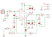
- I have an input cap, you don't.
- Your input impedance is 22K, mine is 56K. Yours gives you slightly less Johnson noise, I get the advantage of using a smaller input cap if I want an input cap at all.
- Your time constant of R4+c7 is at a frequency about double of mine, because I use 47uF and you use 22uF. I personally like the NatSemi datasheet recommendation about the upper and lower cutoffs: they recommend that the lower one should be one-fifth of 20Hz and the upper should be five times 20KHz. Your time constant places you a little closer to 20Hz than what I'd like.
- You have an extra RC combo for the mute pin. I will need to add that when I shift from 3875 to 3886. BTW, someone had recommended something like 70K for the mute resistor... are you sure that value can be changed as widely as 70K to 22K? How does one determine that one's value?
- Your PSU filtering caps are one-fourth the value of mine. Are you sure such small values are preferable? I have no clue other than what the NatSemi datasheet and other diy builders are using. They seem to talk of at least 1000uF per rail.
- You've put the so-called Boucherot network (that R6+C8 combo) and the RL filter at the output of your amp, and I haven't. I'm still undecided whether I should. I'm told by a few experienced constructors that I should put them only if I see/hear any problems in their absence.
tcpip. i actually meant "not" instead of "now". basically that cap on the input is to remove DC from previous stages. if you have a small DC offset from the source/signal processing, then there is no need to block it out. the cap in the feedback, along with the bias resistor, are designed to reduce DC offset from the IC.
Aud_Mot said:I am a little confused.
Output connection X2-1 and X2-2. If the load (speaker) goes between these 2 points, you will not get any potential. Your speaker will see the equivelant of a 12.7 ohm resistor in series with a 100nF cap accorss it's terminals. The amp output just flapping in the wind, with no path to ground.
Maybe there is supposed to be a ground/common connection between the C8 and terminal point X2-1?
A quick look at your PCB seems to refelct what I think is an error in the schematic.
Aud_Mot
I would have to agree here, you appear to have your speaker conected accross your output ressitor and zobel network rather than from your output resistor to ground.
This may simply be because you have forgotten to ti the bottom of the zobel to ground in your schematic, but as it is the circuit shouldn't work very well at all and will need to have this change made before you can use it.
Hi all,
Came back from a very refreshing weekly off and am charged up....
first of all, good to see that the discussion has improved...
now for my questions...
1. are you guys using unregulated power supplies or smps??
2. how do you post images on this forum??
3. and would using a toroidal transformer instead of a E-I core improve the sound quality?? ( why i am asking is because the cost factor is almost 10 times)
Madhu.
In reverse order now...
Madhu,
No, this is not a mistake in the circuit, it's a mistake in my post. I should have explained more clearly (and not type these replies at 2 in the morning!). I return the speaker back to the power supply star ground (midpoint of the capacitors). I also seperately return the zobel network's ground end to the PSU star point through X2-1.
Tarun,
 ) along with a (usually discrete) linear regulator. Audio stuff probably won't need this, though.
Madhu,
- Unregulated supplies for me.
- RTFM! Then use the "Attach file" option below the reply composer.
- Toroid cores have the benefit of reducing fringe fields (the fields are kept within the core much better than EI), so there's less chance of a ground loop or signal loop picking up the field. Another benefit: you can use a slimmer case.
No, this is not a mistake in the circuit, it's a mistake in my post. I should have explained more clearly (and not type these replies at 2 in the morning!). I return the speaker back to the power supply star ground (midpoint of the capacitors). I also seperately return the zobel network's ground end to the PSU star point through X2-1.
Tarun,
- I have an input cap, you don't.
- Your input impedance is 22K, mine is 56K. Yours gives you slightly less Johnson noise, I get the advantage of using a smaller input cap if I want an input cap at all.
- Your time constant of R4+c7 is at a frequency about double of mine, because I use 47uF and you use 22uF. I personally like the NatSemi datasheet recommendation about the upper and lower cutoffs: they recommend that the lower one should be one-fifth of 20Hz and the upper should be five times 20KHz. Your time constant places you a little closer to 20Hz than what I'd like.
- You have an extra RC combo for the mute pin. I will need to add that when I shift from 3875 to 3886. BTW, someone had recommended something like 70K for the mute resistor... are you sure that value can be changed as widely as 70K to 22K? How does one determine that one's value?
- Your PSU filtering caps are one-fourth the value of mine. Are you sure such small values are preferable? I have no clue other than what the NatSemi datasheet and other diy builders are using. They seem to talk of at least 1000uF per rail.
- You've put the so-called Boucherot network (that R6+C8 combo) and the RL filter at the output of your amp, and I haven't. I'm still undecided whether I should. I'm told by a few experienced constructors that I should put them only if I see/hear any problems in their absence.
- My input cap is at the preamp board's output (1+1uF plastic film). Once again, sorry this wasn't mentioned before. You should use an input cap, otherwise the LM3886 bias currents will flow in/out of your preamp.
- This is the problem with dealing with RF designs by day and audio by night. I prefer lower impedances for the lower noise. Not that I can hear it, though!
- The lower cutoff frequency is quite high since most of the bass will end up going into a sub. The amplifier rolling off the lower end will help protect any vented speakers connected to the amp if the crossover (main to sub) is switched off.
- The mute pin stuff was straight out of the LM3886 datasheet. From what I can see, as the cap charges up, it mutes the amp for a while, removing any possible thump which the preamp may have generated.
- No no no!!! These are not PSU filtering caps, these are merely local decoupling to offset the effect of a long cable delivering power to the amp from the main PSU. The PSU itself has a C-R-C structure (4700uF, 0.1 ohm, 4700uF) per channel.
- As for the Zobel, I prefer the opposite. Include it, remove if there are any problems In my limited understanding of this subject, I think they will act like a minimum load for the amp, in addition to compensating for the inductive nature of the speaker cable and voice coil.
- The badly written part on the 50-100 ohm resistor should go something like this: if the input connector to the PA falls off, then the amplifier has no ground reference against which it compares the input voltage. Thus, the output can swing to one of the rails, welding tight any speaker connected to the output. If you connect the grounds together, there *may* be hum (depending on your layout and wiring), so the compromise is to use a resistor between the two grounds (input and power). This way, there is a ground reference even if the input connector is removed. When there is a connector in place, though, the ground path through the connector, to the preamp and back to the PSU star point is much lower in resistance compared to the resistor between the planes on your amp board. Thus, no "ground loop" is formed.
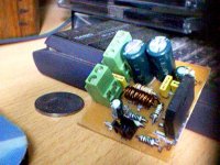
) along with a (usually discrete) linear regulator. Audio stuff probably won't need this, though.Here's a pic of the amp board. That's a 1 rupee coin, for size comparison. The black connector at the bottom is the input connector, the green screw terminals are for speaker and supply voltage. Note the inductor (rather small ) wound around R7. I've used the isolated version of the LM3886 here, since good sil-pads of the right size for a 3886 are hard to come by here.
) wound around R7. I've used the isolated version of the LM3886 here, since good sil-pads of the right size for a 3886 are hard to come by here.Attachments
Oh, okay. I understand clearly now. Thanks for the patience.theChris said:i actually meant "not" instead of "now". basically that cap on the input is to remove DC from previous stages. if you have a small DC offset from the source/signal processing, then there is no need to block it out. the cap in the feedback, along with the bias resistor, are designed to reduce DC offset from the IC.
But I think a lot of people are fanatical about keeping DC offset at the output to single-digit millivolts. I'm not debating whether that fanatical approach is necessary... I was just wondering whether your approach, of cutting DC gain, will be adequate to protect speakers? Just curious.
to protect? well the cases where DC damages speakers is in cases where something has gone horribly wrong. so it's unlikely that anything not specificially designed to protect the speaker will help. this means if you want to ensure the speaker is protected from DC, all you can do is use a fuse, large capacitor, or some other form or protection circuit.
basically, if you look at what causes the DC offset problem, you'll notice that there are 2 places for the DC offset to originate: from the source, and from the amplifer. a large value cap on the input will correct the source issue, and a cap in the feedback path should help the DC offset of the amplifer. without it, any DC offset gets multiplied by the gain of the amplifier.
basically, if you look at what causes the DC offset problem, you'll notice that there are 2 places for the DC offset to originate: from the source, and from the amplifer. a large value cap on the input will correct the source issue, and a cap in the feedback path should help the DC offset of the amplifer. without it, any DC offset gets multiplied by the gain of the amplifier.
- Status
- This old topic is closed. If you want to reopen this topic, contact a moderator using the "Report Post" button.
- Home
- Amplifiers
- Chip Amps
- Lm3886 Pcb