HI,
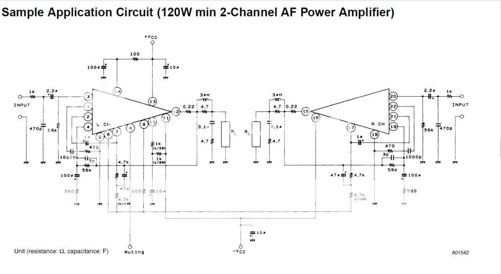
I am replacing the fried powerstage of a Sansui A-60 with a STK4241 Hybrid Chip Amp. Rail volatges are +/-52V. So I understand I can only use 80hm Load. The PCB is exactly like the typical application circuit below
I already wired up a board except the zobel part. I have used 0.33Ohm 5Watts resistor.
Is it okfor me to use a 10µH inductor there at the output instead of the recommended 3µH? I know that's quite a high value. But I have it ready in hand. I have the following from Panasonic.
Specification from element14 as below
CHOKE, 10UH, 3.9A, 0R026
Product Range: PANASONIC - ELC-10D Series
Inductance: 10µH
Inductance Tolerance: ± 20%
DC Resistance Max: 0.026ohm
RMS Current (Irms): 3.9A
Saturation Current (Isat): -
Packaging: Each
Case Dimensions: 10mm x 15mm
Core Material: Ferrite
DC Current Rating: 3.9A
Inductor Case Style: Radial Leaded
Inductor Type: Choke Coil
Lead Spacing: 5mm
No. of Pins: 2
SVHC: No SVHC (16-Dec-2013)
Test Frequency: 10kHz
Is this good enough as the inductor in series to the speaker load? Can I still use a 4.7Ohm resistor to by pass it?
I assume I can also use another 4.7Ohm in series with.1uF to the ground across the speaker load just as in the circuit diagram? I read somewhere than when used with 4Ohm impedence loads(with out even considering the inductance/resistance of the speaker cables), 10uH will result in a 0.4dB attenuation at 20Khz? Will my high end be really affected? Or shall avoid the inductor whole together? But I assume it's necessary to avoid high frequency oscillations.
Sorry even if I know a bit about the LC and RC filter equations I am a bit lost here on which all values to consider when calculating. My network theory fundamentals are rather weak
Another question is what wattage should those 4.7Ohm resistors be?
I assume p/n is ELC10D100E.
Here's a link to the data sheet:
http://www.mouser.com/catalog/specsheets/ELC_Series.pdf
From a power dissipation point of view, it's rated at 3.9 Amps DC. Once again, strictly from I-squared-R dissipation, that says that you could dissipate 3.9 Amps RMS. That comes to be 3.9^2*8=121.7 Watts with an 8 Ohm load.
With a plus/minus 50 volt supply and 8 ohm load, you can deliver max of about 150 Watts...That says, for power dissipation, in the worst case, it's not quite up to the task.
Perhaps of greater concern is that the inductance will vary with signal swing...that will certainly increase distortion. Unfortunately, they give no curves for inductance versus current (or temperature, for that matter).
so...you could use all the typical components and values around it, and it would be ok...just not totally blameless. That there's 10 uH...at 20 kHz, that looks like 1.25 Ohms at 20 kHz...there will be a little rolloff...about 0.1 dB (assumes 8 Ohm load).
So, unless you're trying for ultimate blameless performance, they should work ok.
Djoffe, thanks a lot for reaffirming my decision. I do not see myself running this amp beyond 50Watts per channel. With the current rail-voltage of +/- 43V I surely won't hit 100Watts even at max as there definitely will be a power supply sag also. And yeah I don't think I will use with a load with 8Ohm impedance at 20KHz either. It will be much more higher. So I guess I will be safe in this case.
It can/will saturate on transient peaks... and nonlinearity... its just not the done thing
Your amp circuit is a little unusual. The 0.22 ohm is the one of the main components to aid stability by isolating the amplifier output from capacitive loading. The amp also runs at very high gain (56k/560 feedback factor) which also helps stability. The 0.1uf and 4.7 ohm "Zobel" network isn't technically a Zobel. Its on the wrong side of the inductor for that. It terminates the speaker cable at hf but not the amplifier (as a Zobel would) because of the inductor. The design seems to not need a Zobel (which is unusual) but the other factors I outline obviously render it not required.
Your amp circuit is a little unusual. The 0.22 ohm is the one of the main components to aid stability by isolating the amplifier output from capacitive loading. The amp also runs at very high gain (56k/560 feedback factor) which also helps stability. The 0.1uf and 4.7 ohm "Zobel" network isn't technically a Zobel. Its on the wrong side of the inductor for that. It terminates the speaker cable at hf but not the amplifier (as a Zobel would) because of the inductor. The design seems to not need a Zobel (which is unusual) but the other factors I outline obviously render it not required.
The circuit there is from Sanyo's Data sheet. And I am using it as is. The PCB I have, has provision for an inductor. But not for the bypassing resistor. So I am just soldering the resistor on to the inductor itself. Again the PCB I have doesn't have the RC filter(100nF, 4R7) provision so I am also doing a P2P for that from the output. I am doing all this after reading horror stories of STK chips oscillating. Anyway I am on my way to pick-up an old Oscilloscope and function generator. Few hours later I will power up and see what do I see when fed with a 20KHz sine wave. Including the attenuation. I am happy to have 50W per channel. Because anything above STK produces massive THD like 10%.
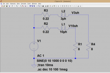
That is something that shows well in simulation.
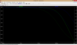
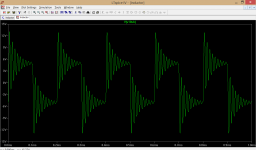
Here is your set up and the response with a 10uh and a 3uh coil. And squarewave of 50kHz into 8 ohms.
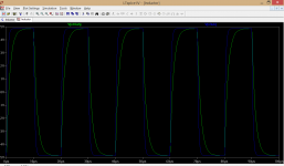
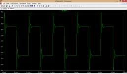
Also, here is the response at 5kHz with a squarewave using the 3uh value and when the amp is loaded capacitively. Look how the parallel resistor damps the ringing (last picture).
Here is your set up and the response with a 10uh and a 3uh coil. And squarewave of 50kHz into 8 ohms.
Also, here is the response at 5kHz with a squarewave using the 3uh value and when the amp is loaded capacitively. Look how the parallel resistor damps the ringing (last picture).
Attachments
Neville Thiele drew up the original requirements for this stability enhancing device..................... The 0.1uf and 4.7 ohm "Zobel" network isn't technically a Zobel. Its on the wrong side of the inductor for that. ...................
Dr Cherry presented a paper (and maybe more) explaining that Thiele's two versions were at the extreme ends of a continuous range of output stability components.
The two original versions are:
A.) R+C to ground followed by L to speaker.
B.) Inductor to speaker terminals and C across speaker terminals.
Both versions work.
I have posted a spreadsheet showing how to calculate the Cherry "range" of components going all the way from A. to B.
Since then I have adopted the Pi version of the Thiele Network and I have now seen a couple of designers recommending this Pi version.
The Pi version consists of:
R+C to decoupling ground very close to the output devices to minimise Loop Area and minimise inductance
L||R in the cable route from amplifier to speaker terminals, with the speaker return lead twisted along again to minimise Loop Area
R+C across the speaker terminals with very short leads (limited by the terminal pitch) to attenuate incoming interference.
Dr Cherry's Thiele discussion paper has also been posted on the Forum.
Last edited:
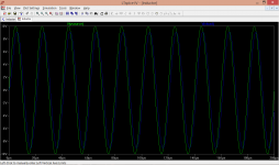
So 10uH is still a very high value? Sorry in the first response graph I can see solid lines and dotted lines for both 3uH(blue) and 10uH(green) inductors. What does dotted line signify? the solid line case, I can see attenuation is less than 0.2dB at 20Khz?
Its phase. This shows the voltage source and the voltage across the load at 50kHz.
Attachments
Neville Thiele drew up the original requirements for this stability enhancing device.
Thanks. I found an old thread on this earlier this morning but didn't read all the details. It mentioned Bob C favouring and R/C network at the speaker terminals too.
Around 1V attenuation at 50Khz? I am happy to barely meet 20Khz as STK chip as such is not an "Audiophile" component. I am getting ready to solder the chip and do the actual measurement on a 20Khz sine-wave through the network.Its phase. This shows the voltage source and the voltage across the load at 50kHz.
Another question I have is about the wattage of R in the R-C across the speakers. For a 100nF film cap, can I get-by with a 0.25W or 0.5W, 4.7Ohm Resistor?
Sorry I am not good when it comes to circuit analysis, but I assume with 4.7Ohm and 0.1uF cap parallel to 8Ohm Load, pass frequency frequency will be something in few hundred Khz? And there will be hardly any current at those frequencies anyway right?
Typically a 2 watt carbon or metal film would be used for the 4.7 ohm. Even that is under rated if you test at high power (sine testing at 20kHz) but for music its fine. A half watt would let you test it all and listen at reasonable level but its way to low for permanent use.
At 20kHz and 10 volts peak (so that's only 6 volts rms) the resistor is passing nearly 125ma peak. Whats that, I squared times R, just under 0.1 watts.
I would fit a 2 watt. The dissipation rises with the square of the voltage.
At 20kHz and 10 volts peak (so that's only 6 volts rms) the resistor is passing nearly 125ma peak. Whats that, I squared times R, just under 0.1 watts.
I would fit a 2 watt. The dissipation rises with the square of the voltage.
Yes, testing is the problem for amplifier Zobels
music where average levels are well below -6dB relative to max power do not heat up the Zobel.
Testing at 1kHz full output voltage does not heat up the Zobel either.
10kHz and above test signal can heat up the Zobel resistor and the Zobel capacitor significantly.
If during this testing, either component goes open circuit then you risk oscillation.
If it's not noticed then when one re-connects the speaker one can end up with blown tweeter/s.
20kHz sees 100nF as ~80ohms
A combination of 10r and 80ohms passes the same as a 80.6ohms impedance.
20Vac (28.3Vpk) would push ~248mAac through these two components.
The resistor would dissipate ~616mW.
An esr of 0.01ohms would dissipate ~0.6mW in the capacitor.
The resistor needs to be big (or many in series/parallel) to survive testing, especially @ 50kHz !!
Yes, testing is the problem for amplifier Zobels
music where average levels are well below -6dB relative to max power do not heat up the Zobel.
Testing at 1kHz full output voltage does not heat up the Zobel either.
10kHz and above test signal can heat up the Zobel resistor and the Zobel capacitor significantly.
If during this testing, either component goes open circuit then you risk oscillation.
If it's not noticed then when one re-connects the speaker one can end up with blown tweeter/s.
20kHz sees 100nF as ~80ohms
A combination of 10r and 80ohms passes the same as a 80.6ohms impedance.
20Vac (28.3Vpk) would push ~248mAac through these two components.
The resistor would dissipate ~616mW.
An esr of 0.01ohms would dissipate ~0.6mW in the capacitor.
The resistor needs to be big (or many in series/parallel) to survive testing, especially @ 50kHz !!
I am stuck again
I do not have any higher watt MFR or CFR. I have this
Dayton Audio DNR-4.0 4 Ohm 10W Precision Audio Grade Resistor
PE says they can be used in Zobel networks. But it's again wirewound.
Other than that, I have a 5Ohm 5W 5% wire-wound or 0.25W and 0.6W 4.7Ohm MFRs in hand. Seems like again have to order/go buy resistors to continue
The below are what I have now. No other smaller values which I can parallel too.. Nearest low value I have to a 4.7Ohm is 100Ohm 0.5Watts. I guess none of them would suffice.
Dayton Audio DNR-4.0 4 Ohm 10W Precision Audio Grade Resistor
4 Ohm 5W Resistor Wire Wound 5% Tolerance
LR0204F4K7 - TE CONNECTIVITY - RESISTOR, METAL , 4K7, 0.25W, | element14 Singapore
MRS25000C4708FCT00 - VISHAY BC COMPONENTS - RES, THIN FILM, 4R7, 1%, 600MW | element14 Singapore
Last edited:
A 0.6 watt, 4.7 ohm film will allow you to prove the amp. It will stay cold for normal listening levels. It will NOT allow testing at full power.
(its like having a Ferrari with tyres of a speed rating of 30mph. If all you do is go down to the local shops then you would never see a problem. Go for a track day and you (read the amp) might not live to tell the tale)
(its like having a Ferrari with tyres of a speed rating of 30mph. If all you do is go down to the local shops then you would never see a problem. Go for a track day and you (read the amp) might not live to tell the tale)
a pair of 10r 600mW resistors in parallel is equivalent to 5r 1.2W
series connect that parallel pair with a second pair and the four resistor are equivalent to 10r 2.4W
Parallel another set of 4 resistors making 8 in all and you have a 5r 4.8W equivalent.
Start with other values than 10r and you can create any value you need at any power that your need.
series connect that parallel pair with a second pair and the four resistor are equivalent to 10r 2.4W
Parallel another set of 4 resistors making 8 in all and you have a 5r 4.8W equivalent.
Start with other values than 10r and you can create any value you need at any power that your need.
- Status
- This old topic is closed. If you want to reopen this topic, contact a moderator using the "Report Post" button.
- Home
- Amplifiers
- Chip Amps
- A Zobel Question on STK4241II