Firstly, having just read all the pages of debate about exotic components and whether or not they are worth it I don't want this thread to end up the same!!
I'd like to hear from people who have used specific component choices in their GC and how they feel it has made improvements.
I am preparing to build my first GC and really don't want to be dissapointed, I will probably be selling my Arcam amp first so there will be no way back!
So far on my list is A GOOD POT, probably Alps Audio grade. Will use one for both channels, as it is surely better than 2 at half the price. And currently only have 1 toroid.
Other parts on my shopping list are MUR840 diodes. Possibly Black Gate caps (need to check price), and I already have five LM3875TF's from NS and an old amp chassis.
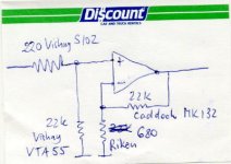
Interested in resistor choices, going for a NI based on this sketch by Peter. Vishay's are expensive, Caddock not too bad, and I can't find Riken anywhere in the UK.
With a Pot added is there any need for the 220ohm resistor? And what is a good ohm value for the pot please?
Regards,
Matt
I'd like to hear from people who have used specific component choices in their GC and how they feel it has made improvements.
I am preparing to build my first GC and really don't want to be dissapointed, I will probably be selling my Arcam amp first so there will be no way back!
So far on my list is A GOOD POT, probably Alps Audio grade. Will use one for both channels, as it is surely better than 2 at half the price. And currently only have 1 toroid.
Other parts on my shopping list are MUR840 diodes. Possibly Black Gate caps (need to check price), and I already have five LM3875TF's from NS and an old amp chassis.
Interested in resistor choices, going for a NI based on this sketch by Peter. Vishay's are expensive, Caddock not too bad, and I can't find Riken anywhere in the UK.
With a Pot added is there any need for the 220ohm resistor? And what is a good ohm value for the pot please?
Regards,
Matt
Attachments
Hi Matt,
Firstly, if you can afford it go with a stepped attenuator as (so I am widely told) that will degrade the signal quality less than a simple pot.
I changed input resistor from a nice Welwyn metal film to a very cheap carbon one and din't notice any difference in sound quality, at least nothing that made me wince!
I don't think you will need the 220R with the pot/stepped attenuator in place.
I use black gates for the input caps (4.7uF) but I had to wait over 6 weeks for them from Audiocom.
BTW, where are you from in Northants? I lived there for 19 years (then off to college!)
I second the suggestion to use a stepped attenuator instead of a pot. IMHO the attenuator is clearly superior.
For the IGC, use the one shown on my Gainclone FAQ page on Decibel Dungeon.
I like a pair of Welwyn RC55 resistors for the feedback and matched carbon films elsewhere.
The Blackgate caps are unlikely to sound that much different to the Panasonic FC's given the huge different in price.
I use the MUR860's for the rectifier bridges and have no inclination to try anything else given the sound of any of my Gainclones.
Do use a transformer for each channel with either one or two bridges.
Use a heavy heatsink, not only for keeping the chip cool but for resonance reasons too.
For an input cap, a polypropylene is ideal.
But do remember that this is all personal taste - there is no ideal recipe other than the one you achieve by trial and error!
carlosfm said:If you use a pot, you don't need the 22k resistor from NI to ground.
If you are using a pot that is more than 20K (like 50k or 100k), you definitely need a 22k shunt resistor at NI input, otherwise the offset jump is pretty high at full volume (300mV or so). This is of course when no cap is used at inverting input.
I also noticed that in some systems, when using a pot, at full volume (no series resistance) the offset increases as well (plus some noise is detectable), that's why I added 220 ohm series resistor.
While pots are OK, using switching attenuator improves the sound substantially. I bought some time ago a Spectrol pot used in one of older ML preamps. This is whole metal body pot, linear with shunt resistor added. The matching between the channels is perfect. I thought this could be a nice sounding one, but to my disappointmet it sounded worse than my Nobles. Eventually I built my own switcher and the best results I obtained with a fixed series/switching shunt resistance. I'm using a parallel combination of 10K AN tantalum and 10K Vishay S102 for a total of 5k series resistance. The shunt switcher consists of Holcos and max resistance here should be 20K or so. I used here my older Sonic Frontiers attenuators valued at 50k with Electroswitch switcher and I'm using additioanly 22k Vishay from NI input to ground, so the shunt resistance never goes higher than 22k, otherwise offset increases.
Regarding the parallel tantalum and Vishay, none of those resistors sound satisfactory when used alone. Tantalum emphsizes the midrange region and provides authority, but alone it's too tubey without enough air. The Vishay, OTOH is too soft sounding, but has very good resolution at highs, together they work very well
")
As to the exotic components in the amp, it's hard to recommend anything really, as for best results they have to be chosen by trial and error in a given setup. While the ones in a drawing work for me, they also work well only with an amp they were tried in (the AMP-1) and in a different setup, they might provide less satisfactory results. The choice depends on attenuator, chassis, PS and even wiring. As always experimentation is recommended.
http://www.diyaudio.com/forums/showthread.php?s=&postid=304433#post304433
Peter Daniel said:
If you are using a pot that is more than 20K (like 50k or 100k), you definitely need a 22k shunt resistor at NI input, otherwise the offset jump is pretty high at full volume (300mV or so). This is of course when no cap is used at inverting input.
I have an LM4780 NIGC, with a 50k log pot.
Initially, I had the 22k resistor.
I removed it and it made a slight difference for the better in sound quality (transparency, detail).
No problems with DC with or without resistor, even at max volume (I always test this).
There are no two equal GCs.

Oh, BTW I remember a detail now:
I don't use an input cap.
But I use a 33uf/40v Philips electro bypassed with 150nf poly from Ri to ground.
The sound is amazing, specially after I bypassed the electrolythic.
And no DC.

This guy has lots of cheap stepped attenuators.
http://cgi.ebay.com/ws/eBayISAPI.dll?ViewItem&item=3071273007&category=39783
http://cgi.ebay.com/ws/eBayISAPI.dll?ViewItem&item=3071273007&category=39783
besides the feedback resistor, which one makes the most difference to sound? I dont want to break the bank! but I want to be convinced by CG when its done
There are only two others!
Make the 220R input a carbon film and you won't be disappointed.neutron7 said:peter daniel,
besides the feedback resistor, which one makes the most difference to sound? I dont want to break the bank! but I want to be convinced by CG when its done
its non inverting
I would say that input series resistor makes least difference (I think). You don't even have to use it, but as mentioned previously, I noticed that in some systems, when volume is at max, sudden jump in offset occurs (up to 300mV).
I just made an interesting discovery yesterday. As you know we had stereo amp and monoblocks at the CES. For some reason the stereo amp played much better at the show and we didn't even play monoblocks as they were not a match for a stereo amp (AMP-1). I wasn't at the Show, so it's not even my observation, but everybody in the room agreed on that. This was very surprising. So yesterday I had a listening session to compare both amps. Indeed, the stereo amp had much better depth of soundstage, the decay was much longer and the speakers were simply disappearing. The monoblock sounded fine, but it didn't produce as much magic as the stereo amp. I suspected two things. The shunt resistor (stereo amp had Caddock MK132 across the pot, monoblocks had Vishay VTA55) and the way the chip was mounted (oxide pad versus silpad with copper bar). Actually, I was almost sure it was the mounting of the chip that made a difference, but since swapping resistors was easier I did it first.
Well, placing Caddock in shunt position at the input, changed the sound drastcally and now the monoblocks had the same sonic signature as AMP-1.
I noticed previously that shunt resistor was quite important, but I didn't expect it was that important.
So for now I go with Caddocks for feedback and shunt and I still use Riken from - input to ground. We tried Caddock in this position before but Riken works much better.
As to the series resistor, you might use it or not, depending on your system, so don't invest too much money into this one, Vishays are pretty expensive
hi Peter
I have some questions for you and others:
- I also plan to make GC dual monoblocks. Ie separate channels for mid and tweeter in each monoblock, powered by a 22-0-22 VAC toroid 150-200VA.
I am at the stage of collecting all the parts so i can start experimenting.
- BTW, Peter, have you seen those nice flat heatsink in Active Surplus? they are aluminum about 10''x8'', they were $10 there (dont have camera, sorry). When I finish those amps I will post a pic for sure.
- How thick should be the copper 'shield' that shields the circuitry from the trafo? (would thick copper foil do?, like the one in active surplus) Also where in TO i can get raw materials for this ?(checked HD)
- So is this the current design, that had been decided the best? (the one in this thread) because I was going to build the one that has 10K and 220K resistors.
I have not got the resistors yet so i am still open to suggestions in this department.
- Also, are there any specific suggestions on the types of resistors to use, if used just for tweeter or mids. (since i will be byamping, might aswell customize)
- Are you still looking for people to join the group purchase of Blackgate NX caps?
- The last but not the least, I saw your link on your stepped attenuator. I have a very nice stereo series (not the ladder ) 24-pos switch on hand. But still need to rig it up with resistors.
So your current recommendation is 20K log?
I was surprised to see your implementation of your SA. Fixed paralleled pair of resistors and variable resistors on the 'ground'.
How did that work out? I never thought that would work, and never saw that configuration anywhere before.
Since i have series type switch, I figured i can do the half-ladder style attenuator if I go the same way, i e half fixed, and variable ground. Also what kind of not very expensive resistors would do good as a variable on the ground?
More info on this or links to it is greatly appreciated!
Thanks
Alex
I have some questions for you and others:
- I also plan to make GC dual monoblocks. Ie separate channels for mid and tweeter in each monoblock, powered by a 22-0-22 VAC toroid 150-200VA.
I am at the stage of collecting all the parts so i can start experimenting.
- BTW, Peter, have you seen those nice flat heatsink in Active Surplus? they are aluminum about 10''x8'', they were $10 there (dont have camera, sorry). When I finish those amps I will post a pic for sure.
- How thick should be the copper 'shield' that shields the circuitry from the trafo? (would thick copper foil do?, like the one in active surplus) Also where in TO i can get raw materials for this ?(checked HD)
- So is this the current design, that had been decided the best? (the one in this thread) because I was going to build the one that has 10K and 220K resistors.
I have not got the resistors yet so i am still open to suggestions in this department.
- Also, are there any specific suggestions on the types of resistors to use, if used just for tweeter or mids. (since i will be byamping, might aswell customize)
- Are you still looking for people to join the group purchase of Blackgate NX caps?
- The last but not the least, I saw your link on your stepped attenuator. I have a very nice stereo series (not the ladder
) 24-pos switch on hand. But still need to rig it up with resistors.So your current recommendation is 20K log?
I was surprised to see your implementation of your SA. Fixed paralleled pair of resistors and variable resistors on the 'ground'.
How did that work out? I never thought that would work, and never saw that configuration anywhere before.
Since i have series type switch, I figured i can do the half-ladder style attenuator if I go the same way, i e half fixed, and variable ground. Also what kind of not very expensive resistors would do good as a variable on the ground?
More info on this or links to it is greatly appreciated!
Thanks
Alex
To shield any circuitry from the magnetic field of a trafo, you need to use u-metal sheets. Copper has no or very little effect in reducing this magnetic field.
here's an example from my supplier http://www.elfa.se/pdf/48/04889101.pdf
pretty expensive stuff
here's an example from my supplier http://www.elfa.se/pdf/48/04889101.pdf
pretty expensive stuff
Peter Daniel said:
I noticed previously that shunt resistor was quite important, but I didn't expect it was that important.
Maby that's why I noticed such a difference (for the better) when I removed it.
carlosfm said:
Maby that's why I noticed such a difference (for the better) when I removed it.
If you use a pot, you actually never remove it
Static,
The shunt attenuator works very well. Here's nice link to calculate the values. http://homepages.tcp.co.uk/~nroberts/shunt.html
I'm using 5K for a series element. You don't have to parallel two resistors to obtain that value, I just didn't like the sound of single ones so by paralleling I achieved better "mixture".
I'm not using heatsinks with my amps, as regular panels dissipate enough heat. If you are looking for copper, brass or bronze, Metal Supermarkets is the place to go.
The design I posted in this thread is the best I've built so far, but this is relative, others might do better.
I'm not interested in BG NX caps. I was using N type for a while, but I don't think they are worth the price.
As to the resistors used in shunt switching, Holcos work well, you might try BC from Digi-Key or some other cheaper brands that partsconnexion carries. But old style Holcos are probably he best for that application. Percyaudio.com still carry the old stock.
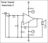
BTW, this is current schematic
The shunt attenuator works very well. Here's nice link to calculate the values. http://homepages.tcp.co.uk/~nroberts/shunt.html
I'm using 5K for a series element. You don't have to parallel two resistors to obtain that value, I just didn't like the sound of single ones so by paralleling I achieved better "mixture".
I'm not using heatsinks with my amps, as regular panels dissipate enough heat. If you are looking for copper, brass or bronze, Metal Supermarkets is the place to go.
The design I posted in this thread is the best I've built so far, but this is relative, others might do better.
I'm not interested in BG NX caps. I was using N type for a while, but I don't think they are worth the price.
As to the resistors used in shunt switching, Holcos work well, you might try BC from Digi-Key or some other cheaper brands that partsconnexion carries. But old style Holcos are probably he best for that application. Percyaudio.com still carry the old stock.
BTW, this is current schematic
Attachments
Peter, et al,
I'm building monoblocks (NI 3875TF) and was not planning on using an attenuator. I would rely on the preamp to control volume.
I was going to go straight from the source input on the amp into the 220k series resister to + input.
Does anyone know, am I going to run into an surprises by not having an attenuator/volume control on the amp?
Thanks -
Bruce
thanks for the replies, Peter
couple of more questions, if you dont mind
- I didnt quite understand when you need the 22K shunt resistor and when you dont. Can you elaborate? Providing that i will use the variable shunt attenuator - similar to yours.
- So you say you found 20K value for the input pot to be the best?
But when i use the calculator you gave me, it tells me to use 20K series resistor on the input (Rx). Is that what i should do?
- Mad_k mentioned that I need mumetal for shielding. I heard somewhere that there are at least two types of fields that might negatively effect the circuitry, the magnetic and some other one (RFI?).
Also i heard that MUmetal is the best for magnetic but alum or copper, is good for that other field. And as far as i am concerned, toroid type of trafo creates much less magnetic field.
- Is it a bad idea to use Riken on feedback? I ask because thats what i have in my MC upgraded Hafler amp. Maybe i should change it to Caddock.
Thanks a lot for the info
Cheers
Alex
abpea said:Peter, et al,
I'm building monoblocks (NI 3875TF) and was not planning on using an attenuator. I would rely on the preamp to control volume.
I was going to go straight from the source input on the amp into the 220k series resister to + input.
Does anyone know, am I going to run into an surprises by not having an attenuator/volume control on the amp?
It is 220 ohm series resistance. As long as you go with a schematic I posted, I don't see any problems. My monoblocks don't have a pot at the input either.
static said:
- I didnt quite understand when you need the 22K shunt resistor and when you dont. Can you elaborate? Providing that i will use the variable shunt attenuator - similar to yours.
- So you say you found 20K value for the input pot to be the best?
But when i use the calculator you gave me, it tells me to use 20K series resistor on the input (Rx). Is that what i should do?
- Mad_k mentioned that I need mumetal for shielding. I heard somewhere that there are at least two types of fields that might negatively effect the circuitry, the magnetic and some other one (RFI?).
Also i heard that MUmetal is the best for magnetic but alum or copper, is good for that other field. And as far as i am concerned, toroid type of trafo creates much less magnetic field.
- Is it a bad idea to use Riken on feedback? I ask because thats what i have in my MC upgraded Hafler amp. Maybe i should change it to Caddock.
From my experience, if you use 22k for feedback and no cap on - input, if you increase shunt resistance much over 22k (fo instance when using 50k pot), the offset increases as well. So the main reason for 22k shunt resistor is to set the input impedance. If you use 20k pot, 20k is max resistance the amp's "see" at the input so there is no need for additional shunt resistors.
Whatever you use to shield transformer, it will bring improvement in some ways. I don't see much reason to go for mu-metal. Forum member, planet10, was selling at one time self adhesive sheets of that material.
I tried Riken at the feedback position (on GC), but to me, Caddock works much better.
PS: The calculator is good for finding shunt values. You have to choose series value yourself. This type of attenuator will never have fixed resistance and it will change depending on the setting. However, I find that using 5k for series element gets me close to 20k regular pot impedance characteristic at the settings I'm using most frequently.
- Status
- This old topic is closed. If you want to reopen this topic, contact a moderator using the "Report Post" button.
- Home
- Amplifiers
- Chip Amps
- Exotic component choice for a GC