yes, agreed...
Are you agreeing that the Source needs the buffer if it can't drive the cables and receiver (power amplifier)?I built numerous lm1875 amps (close to dozen) and inverting with buffer always sounds better. ...........
.
I don't know anything about the amp you posted, but sometimes sellers do post schematics, and the LM1875 boards I've seen followed TI's "Typical Applications" circuit very closely. It's the first circuit illustrated in the TI data sheet, which is here: http://www.ti.com/lit/gpn/lm1875
Getting to buffers, the problem with older JFETs (famously, the TL072) is that they don't have the best fidelity. Newer JFETs have changed that, but they're relatively expensive.
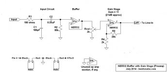
I'm guessing that what you need is a preamp with highish input impedance, a "buffer with gain" so to speak? I'm posting a circuit I use, along with some circuit notes. I hope this might be of some help.
Circuit notes:
R1 is overcurrent protection for the NE5532.
C1 working with R1 forms a low-pass filter that shunts high (over 100kHz) frequencies to ground.
C2 blocks DC.
R2 sets the input impedance, and working with C2 forms a high-pass filter, also called a bass rolloff filter. Here the input impedance is 56k, and rolloff starts at just over 20 Hz, but the C2-R2 combination can be whatever you need.
U1a is a buffer with unity gain, extremely high input impedance, and extremely low output impedance. The buffer isolates the input source from the following circuit. It effectively "looks at" the input source, and reproduces it without affecting it. That is, the input source thinks it has little or no load on its output.
Rvol is the volume control.
U2b is a gain stage, which here is arbitrarily set at a gain of 11 (21 dB). Gain can be almost anything theoretically, but keep it to 20 or so in the real world. The formula is simply R3 divided by R4, then add 1. That is:
Gain = R3/R4 + 1
For preference, leave R4 at about 2k and adjust R3. Higher resistance for R3 = more gain.
The output of this circuit is low impedance, and should be suitable for the line-in input of a mixer, preamp, or amp. If you use this circuit with TI's LM1875 "Typical Application," then the output of this circuit connects to TI's Vin point (the top of R1) without any additional components.
.
I don't know anything about the amp you posted, but sometimes sellers do post schematics, and the LM1875 boards I've seen followed TI's "Typical Applications" circuit very closely. It's the first circuit illustrated in the TI data sheet, which is here: http://www.ti.com/lit/gpn/lm1875
Getting to buffers, the problem with older JFETs (famously, the TL072) is that they don't have the best fidelity. Newer JFETs have changed that, but they're relatively expensive.
I'm guessing that what you need is a preamp with highish input impedance, a "buffer with gain" so to speak? I'm posting a circuit I use, along with some circuit notes. I hope this might be of some help.
Circuit notes:
R1 is overcurrent protection for the NE5532.
C1 working with R1 forms a low-pass filter that shunts high (over 100kHz) frequencies to ground.
C2 blocks DC.
R2 sets the input impedance, and working with C2 forms a high-pass filter, also called a bass rolloff filter. Here the input impedance is 56k, and rolloff starts at just over 20 Hz, but the C2-R2 combination can be whatever you need.
U1a is a buffer with unity gain, extremely high input impedance, and extremely low output impedance. The buffer isolates the input source from the following circuit. It effectively "looks at" the input source, and reproduces it without affecting it. That is, the input source thinks it has little or no load on its output.
Rvol is the volume control.
U2b is a gain stage, which here is arbitrarily set at a gain of 11 (21 dB). Gain can be almost anything theoretically, but keep it to 20 or so in the real world. The formula is simply R3 divided by R4, then add 1. That is:
Gain = R3/R4 + 1
For preference, leave R4 at about 2k and adjust R3. Higher resistance for R3 = more gain.
The output of this circuit is low impedance, and should be suitable for the line-in input of a mixer, preamp, or amp. If you use this circuit with TI's LM1875 "Typical Application," then the output of this circuit connects to TI's Vin point (the top of R1) without any additional components.
.
Attachments
Last edited:
Are you agreeing that the Source needs the buffer if it can't drive the cables and receiver (power amplifier)?
I once tried to run inverting lm1875 (thorsten L circuit) without the buffer from preamp with pretty low output impedance (can drive headphones) and it did not work well...the problem is all between the preamp and chipamp is part of the feedback loop. That makes feedback loop enormous...the buffer effectively separates and shortens the feedback loop of inverting gainclone. My personal opinion, buffer is always required for inverting configuration.
Are you agreeing that the Source needs the buffer if it can't drive the cables and receiver (power amplifier)?
The issue with inverting amplifiers Andrew, is that any nonlinearities in the output impedance of the source will be directly translated into the frequency and phase response of the amplifier. The output impedance of the source is part of the feedback network; draw the Thevenin equivalent circuit to convince yourself. This phenomenon is exacerbated by the use of small value resistors in the feedback network, which we all do for very good reasons.
This is probably why non-inverting amplifiers are preferred by designers. They amplify voltage; not current. They also offer a much higher input impedance and will virtually never require a buffer for practical application.
Of course there are advantages to an inverting circuit that people like us are interested in. In these circumstances the use of a unity gain non-inverting input buffer will offer reliable, "fool-proof" performance.
If you look at commercial designs, circuits like active tone controls (always an inverting circuit to the best of my knowledge) are usually buffered; the preamp gain stage can be an adequate buffer if implemented correctly. That's why you see the tone controls after the gain stage quite often; it avoids employing a dedicated buffer.
Yes, buffers are handy when the input impedance is very low. This is typical of inverting.
The Source impedance can be swamped by selection of an appropriate output resistor. 51r completely removes the effect of output impedance of the driving amplifier where the output impedance may vary from 0.01ohms to 10ohms over the frequency range of 1Hz to 10MHz.
Careful selection completely removes your objection to indeterminate output impedance
any nonlinearities in the output impedance of the source will be directly translated into the frequency and phase response of the amplifier.
Look back at my Thread from about 6 to 7 years ago where we discussed input topologies and their effects on gain and grounding.The issue with inverting amplifiers Andrew,....................... The output impedance of the source is part of the feedback network;
It turned into a grounding discussion.
If you have an inverting chipamp and disconnect the source then the noise gain suddenly becomes too low (say unity) and its highly likely to oscillate. Some kind of RC network from inverting input to GND is called for to maintain stability in the event the input is disconnected.
Yes, buffers are handy when the input impedance is very low. This is typical of inverting.
Yes Andrew, that is true; but that is not the issue. Most modern preamplifiers can drive 600 ohms, which is low enough for a practical inverting configuration.
The Source impedance can be swamped by selection of an appropriate output resistor. 51r completely removes the effect of output impedance of the driving amplifier where the output impedance may vary from 0.01ohms to 10ohms over the frequency range of 1Hz to 10MHz
Yes Andrew, and all that nonlinear impedance plus the 51 ohm swamping resistor are in series with the feedback network. For a 600 ohm input impedance that is a 10% error in the beta gain right out of the box.That is the point. That is why an inverting amp will sound different when driven from different sources. That is why you must insure that your inverting amp is properly buffered at all times that it is powered up. That is why if you build an inverting "gainclone" it is mandatory to use an input buffer.
The issue with inverting amplifiers Andrew, is that any nonlinearities in the output impedance of the source will be directly translated into the frequency and phase response of the amplifier. The output impedance of the source is part of the feedback network...
I used to delight in this and create two or three stages (4 inc. I/V!) of inverting designs, thus creating multiple feedback loops that even the most advanced super computers couldn't calculate!11! Bwhahahaha!!1!

Very few pre-amps/buffers/Sources are capable of driving 600ohms to the levels that typical Power amps need to reach clipping.Yes Andrew, that is true; but that is not the issue. Most modern preamplifiers can drive 600 ohms, which is low enough for a practical inverting configuration.
......................
2V2 from a CDP into 600ohms is equivalent to 5mApk just to drive the resistance.
Then add on an allowance for driving the RF attenuation that should always be fitted.
Then add on an allowance for cable capacitance.
if your inverting amp has a 600r lower leg resistance and the gain is set by the upper leg to 1 by a matching 600r resistance, then the gain is actually 600/(600+Rs)................, and all that nonlinear impedance plus the 51 ohm swamping resistor are in series with the feedback network. For a 600 ohm input impedance that is a 10% error in the beta gain right out of the box.That is the point. That is why an inverting amp will sound different when driven from different sources. That is why you must insure that your inverting amp is properly buffered at all times that it is powered up. That is why if you build an inverting "gainclone" it is mandatory to use an input buffer.
When Rs is 51+0.1Ohm in the audio band, then the actual gain is 600/651.1 = -0.71dB
When the Rs increases to a max of 1ohm in the audio band then the gain becomes 600/652 = -0.72dB
Many Members will not be able to measure this at 20 or 30kHz.
Certainly no Member will be able to hear the 20kHz roll-off of -0.01dB
By the time the Rs has risen to 10ohms at 1Mhz the roll-off will have increased to -0.13dB (-0.71 -{-0.84})
A little bit of VHF attenuation thrown in for free to add to the RF attenuation that will be inserted.
You DON'T need a buffer at the input of an inverting stage to normalise the gains against slight variations in source impedances when the Rs is swamped with an appropriately chosen output resistor.
You will usually find an output resistor in pre-amps/Sources etc. often between 10r and 220r.
Yes Andrew, you do get the point.
I try to make things that are foolproof as possible and more versatile. That is why I would not make an inverting amp that did not have some kind of buffering under all conditions. For example, I might make an integrated amp that relies on the preamp section to buffer the inverting power amp. But if I made an inverting power amp with the input connected to an RCA jack, I would always use a buffer. Same with an integrated amp configured with a preamp out/power amp in (typical of many commercial designs).
What happens if you disconnect the input of an inverting amp, Andrew? I design to avoid this under all modes of use.
Last edited:
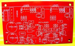
while the discussion is great, I did some more digging...
actually, that circuit is transconductance amplifier
just look closer on the board, I traced 220 ohm accross the speaker output with 0.22 ohm/3 watts resistor to the ground
actually, that circuit is transconductance amplifier
just look closer on the board, I traced 220 ohm accross the speaker output with 0.22 ohm/3 watts resistor to the ground
Attachments
What happens if you disconnect the input of an inverting amp, Andrew? I design to avoid this under all modes of use.
Two fairly compelling reasons for the buffer ISTM - higher input impedance (with no noise penalty) and no oscillation on input disconnect. What's not to like about including one?
- Status
- This old topic is closed. If you want to reopen this topic, contact a moderator using the "Report Post" button.
- Home
- Amplifiers
- Chip Amps
- lm1875 with jfet buffer