I have a buddy working a jobsite where he's replacing a dozen or so of these. He's offered me one if I can use it.
I'm still absolutely new to anything mains...and this sucker is huge. Is this too much for a gainclone?
http://www.altronix.com/products/installation_instructions/T2428300E.pdf
I'm still absolutely new to anything mains...and this sucker is huge. Is this too much for a gainclone?
http://www.altronix.com/products/installation_instructions/T2428300E.pdf
No, its only 24/28 volt ac. Just be sure to add a suitable fuse on the secondary output and its fine.
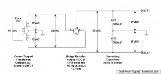
There is one "problem" you haven't mentioned... its a single winding and so the amp will have to be AC coupled, and run on a single 40 volt rail... or... you use two transformers to give -/+40 volts dc. And you have the option of using the lower voltage tap to give around 33 volts dc, so -/+66 volts dc.
There is one "problem" you haven't mentioned... its a single winding and so the amp will have to be AC coupled, and run on a single 40 volt rail... or... you use two transformers to give -/+40 volts dc. And you have the option of using the lower voltage tap to give around 33 volts dc, so -/+66 volts dc.
So...basically I need to choose whether to use 24 or 28...then get a second transformer and use the same. I know with dual windings you create a ground rail from one one of each...what do you do in this case? Run it to mains ground?
Thanks...and sorry for the dumb questions.
Thanks...and sorry for the dumb questions.
Its no problem ")
Right... you need to draw up your design goals. A single rail AC coupled amp (that is using one transformer) will give you one DC rail of 40 volts. Realistically that would give you around 18 watts rms into 8 ohms... so if its a first project then that could be a good option. And 18 watts is louder than you might think.
To use two transformers simply involves joining the secondary's in series with the centre join becoming the zero volt (ground) point. That would give you up to -/+40 volts dc which would deliver around 70 watts rms.
Mains ground is safety ground. You don't automatically have to connect the amplifier circuitry directly to that point, but for a diy build the metal casework should be connected to mains ground. It would be normal to then connect the single "star" ground of the low voltage side of things to that point to.
Thanks...that answers another of my completely unrelated questions about star grounding. I wasn't sure if the grounding on the amp side...going to a star ground...was supposed to connect to safety ground. You're saying its ok to do that?
Yes, its OK to do that, and its also OK to not connect or to connect it via a low value resistor (say 10 ohm).
Confusing isn't it
The reason for perhaps adding a low value resistor between the audio ground (the star) and the main chassis is to prevent ground loops. It still ties the chassis to ground as far as shielding and so on but isolates ground loops.
Its one of those things that has no hard and fast rules.
The important things are that the metal chassis has a direct connection to the main ground. That's for safety, and because you and me as a diy builder can not construct an amp to "double insulated" standards. They are the ones that have just a twin core mains lead. Well, lets say it would be difficult to do. So grounding the case makes it safe no matter what.
What you do on the secondary side is what works best. If the amp has direct ground connections and the CD player/turntable/tuner etc also have similar arrangements then you could well end up with mains hum. Hum due to ground loops is very distinctive, its a pure deep 50/60Hz tone.
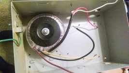
As a follow-up...I got one of the transformers today. Heavy sucker.
Its actually wired and diagrammed in the box differently than it is on the spec sheet I posted the link to. Rather than only having a 24v and 28v out, there's a common out as well. I guess I'm still kinda screwed either way without another one, right?
Its actually wired and diagrammed in the box differently than it is on the spec sheet I posted the link to. Rather than only having a 24v and 28v out, there's a common out as well. I guess I'm still kinda screwed either way without another one, right?
Attachments
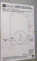
The first diagram just showed the end result for the user, either 24 or 28 volts.
You always take the common as one lead, and then use either the 24 or 28 volt tapping depending what you want.
Although these transformers are electrically OK for what you want (and you do need two) I can't help but think that if you are making a gainclone as a usable domestic amp then it might be worth getting a smaller single tranny. It is going to be really heavy and bulky for one thing and need a large case.
Sorry to drudge this one up from page 3. I was talking this project over with our electrician and he asked why I couldn't just run two wires from either the 24 or 28 secondary and get my two rails that way. I'm sure there's some reason, and its probably over my head. But...I have to ask. Any reason I can't do that?
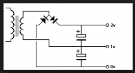
Well using a half wave bridge rectifier you can actually create a dual supply from a single winding but its not a good solution because the rails will be electrically noisy from the half wave action and prone to poor regulation as more current is drawn.
Ask your electrician to draw what he means I seem to remember (there have been a zillion posts since this thread) that you needed a split supply for a chip amp.
This shows how its done with a half wave bridge. 1v would be the zero line with a plus rail above and a minus rail below.
Ask your electrician to draw what he means
I seem to remember (there have been a zillion posts since this thread) that you needed a split supply for a chip amp.This shows how its done with a half wave bridge. 1v would be the zero line with a plus rail above and a minus rail below.
Attachments
.
<< ...why I couldn't just run two wires from either the 24 or 28 secondary and get my two rails that way... >>
The two rails (whether AC or DC) have to be at voltages that are numerically equal, but opposite in polarity. They "have to be" because you say so, that's the final result you want.
The 24 and 28 voltages are not numerically equal, and they have the same polarity.
That's not really clear, is it? Better answer: no, that won't work.
.
Last edited:
.
The two rails (whether AC or DC) have to be at voltages that are numerically equal, but opposite in polarity. They "have to be" because you say so, that's the final result you want.
.
Thanks.That makes PERFECT sense.
I guess I need to cut my losses with this free transformer and just go out and buy the right one.
.
That might be easier this time around, but all these guys have been steering you right from the gitgo. A "center tapped transformer" is essentially two non-center-tapped transformers placed side by side.
Looking at the pictures you posted, with two of these transformers the sheathed white and red wires are the primary side that connects to 120 volt line power. Both whites go together, and connect to one of the AC power wires. Then both reds go together, and connect to the other AC power wire. Electricians say "green is ground the world around," the green wire, if present, never connects to power.
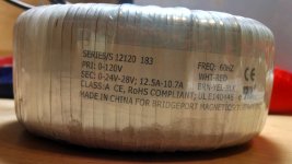
On the secondary (low voltage) side you'd wirenut (cap off, terminate) the black wire, which is the 28 volt wire, if I'm reading the transformer label correctly. Then your 24 volts is the brown and yellow wires.
All of this relates directly to the diagram in post #13. Two 24 volt transformers side by side, for a total of 48 volts. That rectifies to 66 volts DC total, which you use as +/- 33VDC. Yes Mooly, you already said this, but I'm saying it in a different language.
These voltages are too high for an LM1875, but you could run an LM3875 amp off that +/- 33VDC. The "Typical Application" circuit on page two is almost ridiculously simple: http://www.ti.com/lit/gpn/lm3875
However, the LM3875 is going to need a honkin' heat sink. Plan for that before you do anything else. Heat sink & fan combinations made for computer CPUs have been used. https://mrsturgeon.wikispaces.com/file/view/heatsink-and-fan.png/134027999/heatsink-and-fan.png
If you do decide to buy a transformer, I'm going to sound off with my 2 cents and say that toroids (the kind of transformer in your pictures) are all advertising, no delivery. A much less expensive, ordinary power transformer will do the job just fine. Ummm...others do not hold this view.
.
That might be easier this time around, but all these guys have been steering you right from the gitgo. A "center tapped transformer" is essentially two non-center-tapped transformers placed side by side.
Looking at the pictures you posted, with two of these transformers the sheathed white and red wires are the primary side that connects to 120 volt line power. Both whites go together, and connect to one of the AC power wires. Then both reds go together, and connect to the other AC power wire. Electricians say "green is ground the world around," the green wire, if present, never connects to power.
On the secondary (low voltage) side you'd wirenut (cap off, terminate) the black wire, which is the 28 volt wire, if I'm reading the transformer label correctly. Then your 24 volts is the brown and yellow wires.
All of this relates directly to the diagram in post #13. Two 24 volt transformers side by side, for a total of 48 volts. That rectifies to 66 volts DC total, which you use as +/- 33VDC. Yes Mooly, you already said this, but I'm saying it in a different language.
These voltages are too high for an LM1875, but you could run an LM3875 amp off that +/- 33VDC. The "Typical Application" circuit on page two is almost ridiculously simple: http://www.ti.com/lit/gpn/lm3875
However, the LM3875 is going to need a honkin' heat sink. Plan for that before you do anything else. Heat sink & fan combinations made for computer CPUs have been used. https://mrsturgeon.wikispaces.com/file/view/heatsink-and-fan.png/134027999/heatsink-and-fan.png
If you do decide to buy a transformer, I'm going to sound off with my 2 cents and say that toroids (the kind of transformer in your pictures) are all advertising, no delivery. A much less expensive, ordinary power transformer will do the job just fine. Ummm...others do not hold this view.
.
Last edited:
That is a very nice transformer!!!
It would be perfect for something like a Class A amplifier design such as the Pass Labs Aleph X or even a JLH or something.
However you could still use it on single ended supply chipamp configurations just fine.
The ones that use output capacitors.
Or, it can work nicely for a bridged amplifier such as the BA100 or even a BPA200 or something.
There are many other avenues for you to consider as the 28v winding will give you about 39-40Vdc!!
jer
Last edited:
Well, my plan was to purchase a toroid off parts express, but, of course I had to go off and get more complicated. I was at Lowes looking on the clearance shelf and picked up a pair of these.
LINK
I am assuming that I would use the 24v wiring. Assuming the two connections are A and B, I'd take A from one and wire to one rail. B from the other, wire it to the other rail, then take B from the first, and A from the second, and wire those to the ground rail together?
Assuming that to be correct, isn't that wiring these two in series doubling the voltage? Or, does making the "inside" leads the ground rail not double the voltage?
- Status
- This old topic is closed. If you want to reopen this topic, contact a moderator using the "Report Post" button.
- Home
- Amplifiers
- Chip Amps
- Can I use this transformer for lm3886 based amp?