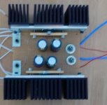
In assembling my LM3886 Chipamp (inverting gainclone), I attached the LM3886 to a heatsink via a brass bar (as well as the standard mounting hole) like this:
To get good heat transfer, I tightened the screws holding the brass bar very tight as well as the screw holding in the chip at the top. This thing is mounted good, very good, to the heat sink...
Then I read a datasheet (for something else) that gave a spec for max force applied to the package, that got me thinking...maybe I tightened this too much? Do you think that's possible? Anyone ever break a chip via overtightening? Recommendations? Worries?
An externally hosted image should be here but it was not working when we last tested it.
An externally hosted image should be here but it was not working when we last tested it.
To get good heat transfer, I tightened the screws holding the brass bar very tight as well as the screw holding in the chip at the top. This thing is mounted good, very good, to the heat sink...
Then I read a datasheet (for something else) that gave a spec for max force applied to the package, that got me thinking...maybe I tightened this too much? Do you think that's possible? Anyone ever break a chip via overtightening? Recommendations? Worries?
Actually, I think what you've done is very clever--the part of the chip that will actually get the hottest, has the best contact with the heatsink. Well done!
There's probably not any danger in mounting it like that, unless you hear the chips crack. I don't think you're going to tighten them that much though.
There's probably not any danger in mounting it like that, unless you hear the chips crack. I don't think you're going to tighten them that much though.
lgreen, I had a strange feeling of dejavu on reading this thread. Did you by any chacne happen to see one I started a month or so ago?
http://www.diyaudio.com/forums/showthread.php?s=&threadid=22254
P.S. how did you get the stainless steel mounting clips off your heatsinks?
http://www.diyaudio.com/forums/showthread.php?s=&threadid=22254
P.S. how did you get the stainless steel mounting clips off your heatsinks?
Attachments
bigparsnip said:
P.S. how did you get the stainless steel mounting clips off your heatsinks?
screwdriver...
bigparsnip said:Nope, mine appear to be held on quite securely with a stainless pin pushed into the heatsink itself (i tried to drill them out and they blunted my drill bit, hitting them had just as much effect).
heh.. his were different then..
lolI like how you have mounted the chips but after reviewing the National LM4731 datasheet I think that you have possibly over tightened the mounting screws. (the LM4731 is a simular package to the LM3886 and has detailed mounting instructions in it - page 12)
I like the clamp/bar, but if I was using it I would torque the single top mounting screw very lightly. As the package heats up and cools down it will flex some and the combination of clamp/top mounting arrangement might cause stress to the package.
I found a small dial torque wrench in a Pawn shop for $10.00 a few years ago and it has come in handy every so often.
Heatsinks- reply
Bigparsnip, I have not seen your earlier thread, but my amp looks surprisingly similar to yours, I even put the torid in last night ... and its in the same spot as you. I don't have as many inputs or any PCBs, and I have 8 diodes rather than bridges. You will notice the resemblence when I am done in a month and post the results, even though I did mine on my own.
As for the clips on the heat sink, I bought my heat sinks without any clips, so didn't have to remove anything. Well that's not true, there were 2 tiny pegs that I removed with a drill, just drilled a tiny starter hole into them then used a bigger bit and made a bigger hole.
My design is + and - 35 V and it does get hot, at least it did the only time I turned it on and drove the heck out of a 5 ohm resistor.
I have these heat sinks:
puchased here
http://sales.goldmine-elec.com/prodinfo.asp?prodid=3547
As I stated on this thread
http://www.diyaudio.com/forums/showthread.php?postid=292577#post292577
Your design looks great, nice work.
Bigparsnip, I have not seen your earlier thread, but my amp looks surprisingly similar to yours, I even put the torid in last night ... and its in the same spot as you. I don't have as many inputs or any PCBs, and I have 8 diodes rather than bridges. You will notice the resemblence when I am done in a month and post the results, even though I did mine on my own.
As for the clips on the heat sink, I bought my heat sinks without any clips, so didn't have to remove anything. Well that's not true, there were 2 tiny pegs that I removed with a drill, just drilled a tiny starter hole into them then used a bigger bit and made a bigger hole.
My design is + and - 35 V and it does get hot, at least it did the only time I turned it on and drove the heck out of a 5 ohm resistor.
I have these heat sinks:
An externally hosted image should be here but it was not working when we last tested it.
puchased here
http://sales.goldmine-elec.com/prodinfo.asp?prodid=3547
As I stated on this thread
http://www.diyaudio.com/forums/showthread.php?postid=292577#post292577
Your design looks great, nice work.
Mine also have the two small pins on the flat side, but through shere chance I was luckey enough that me main cap just fit in between them. I also should be finished mine soon (there was a slight hold up when I became a little over-eager in trimming down my switch posts to fit my knobs) so I look forward to seeing just how similar they are.
PS you aren't using a cast box for the housing as well by any chance are you?
PS you aren't using a cast box for the housing as well by any chance are you?
Box
Bigparsnip,
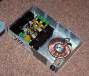
Well, since you asked, here is my housing.
It doesn't look nice now, but it will. This is obviously not cast iron, in fact its a Kyocera CD player chassis with the insides removed. I bought 2 of these cd players on ebay for $35, one was advertised broken, so I gutted it. I might gut the other one to make something that matches. Its going to look "nice" with the wood side panels and the aluminum front panel that I am working on. The felt pads you see are to make the 500 VA transformer level, since the case is not flat.
Do you see the pattern of ventilation holes I put under the heat sink? Are you doing the same thing? I put some holes between the sink sections so that the fins would not block the air flow. I don't have too many since I got sick of drilling. The circled holes are for the threaded holes in the sinks, I drilled and threaded 4-40 holes on the bottom of the heat sinks and will fasten them to the case from underneath.
Bigparsnip,
Well, since you asked, here is my housing.
An externally hosted image should be here but it was not working when we last tested it.
It doesn't look nice now, but it will. This is obviously not cast iron, in fact its a Kyocera CD player chassis with the insides removed. I bought 2 of these cd players on ebay for $35, one was advertised broken, so I gutted it. I might gut the other one to make something that matches. Its going to look "nice" with the wood side panels and the aluminum front panel that I am working on. The felt pads you see are to make the 500 VA transformer level, since the case is not flat.
Do you see the pattern of ventilation holes I put under the heat sink? Are you doing the same thing? I put some holes between the sink sections so that the fins would not block the air flow. I don't have too many since I got sick of drilling. The circled holes are for the threaded holes in the sinks, I drilled and threaded 4-40 holes on the bottom of the heat sinks and will fasten them to the case from underneath.
Yes, I have drilled a lot of holes into my casing (it's cast aluminium) to ventilate it and cool the heatsinks. I think that overall there are close to 500 3mm holes in the top and bottom for this, all of which where centre punched, then pilot drilled with a 1mm bit before being drilled out to their full size (That took a very long time, but it kind of looks cool, and I should have some more pics to post soon).
nope, the one I built uses the LM3875 chips so it is a totaly different PCB which was supposed to fit well into the box I have, only problem is that I should have made it a bit smaller.
But, at the momnet it has still not been turned on due to some general laziness by me when it comes to getting round to finish it, so I can't say for certain how either PCB works or sounds.
But, at the momnet it has still not been turned on due to some general laziness by me when it comes to getting round to finish it, so I can't say for certain how either PCB works or sounds.
- Status
- This old topic is closed. If you want to reopen this topic, contact a moderator using the "Report Post" button.
- Home
- Amplifiers
- Chip Amps
- Mounting the Chip Amp- Overtightening?