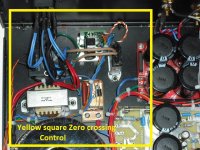
This is an update on my worked on protecting the speakers and preventing/minimizing the inrush current using a micro controller. Protecting the speakers from high current was the easy one. After some researched found that the ACS 712 Hall effect sensor was the ideal one for the application because the simplicity an easy to incorporate in the design. Also you can buy low prices modules already assembled. For the preventing the inrush current I decided to use the zero crossing to ramp the AC up/down when powering the amplifier ON/OFF. After some trial and errors I was able to sync the programming with the zero crossing while ramping the AC voltage up/down. By doing so it would prevent/minimize the inrush current when powering the amplifier. The system it is been running for at least a year with no problems. The above mentioned was installed in my first LM3886 amplifier built with some other features explained as follow:
1- Monitor the speaker’s current and open the speaker output relay if it reached the trip setting. On this built I used a mechanical relay to protect the speakers
2- Ramp the AC up/down on power ON/OFF at zero crossing to minimized the inrush current.
3- Mute the speaker’s on power ON/OFF.
4- Monitor the heat sink temperature and open the speaker relay output if it reached the trip setting.
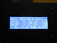
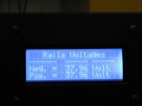
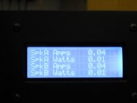
5- Display the current, watts and temperature.
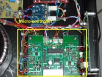
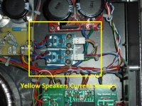
After some members advised replaced the mechanical relay with an SSR. Still the other features were implemented. After some thinking I decided to remove the SSR and let the micro controller control the rails voltage. The micro will be evenly ramps the rails voltage UP/DOWN after the amplifier it is powered ON/OFF. If while monitoring the current the output reached the trip setting, the micro would immediately shutdown the rail voltages preventing any damaging to the speakers. The evenly ramps of the rails voltage also will eliminate the use of the mute on power ON/OFF and prevent /eliminate the speakers “thumps” when the amplifier it is turning ON/OFF. Another featured is the used of the micro to control/regulate/maintain the rails voltage to a predetermined set point. Right now it is set to control the rails voltage to 38.00 volt. By controlling the rails voltage with the micro the SSR it is not longer needed and will eliminate any sound degradation due to the relay contacts going bad. Also relocated the current sensor from reading the current to ground to read it when going out to the speakers. In this way the speakers are protected from high current in case that the outputs are accidentally shorted to ground. Attached are some pictures showing some displays and how the LM3886 was built. The amplifiers it is on beta test to check for software bugs.
Please, keep in mind that I am not expert in transformers. The design of preventing /minimizing the inrush current was done by researching the transformer manufactures applications/ theories notes and write outs.
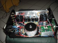
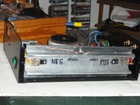
Attached are some pictures showing the amplifier built. Most of the time pictures are better than words. Especially when I am not a technical writer but I tried my best.
1- Monitor the speaker’s current and open the speaker output relay if it reached the trip setting. On this built I used a mechanical relay to protect the speakers
2- Ramp the AC up/down on power ON/OFF at zero crossing to minimized the inrush current.
3- Mute the speaker’s on power ON/OFF.
4- Monitor the heat sink temperature and open the speaker relay output if it reached the trip setting.
5- Display the current, watts and temperature.
After some members advised replaced the mechanical relay with an SSR. Still the other features were implemented. After some thinking I decided to remove the SSR and let the micro controller control the rails voltage. The micro will be evenly ramps the rails voltage UP/DOWN after the amplifier it is powered ON/OFF. If while monitoring the current the output reached the trip setting, the micro would immediately shutdown the rail voltages preventing any damaging to the speakers. The evenly ramps of the rails voltage also will eliminate the use of the mute on power ON/OFF and prevent /eliminate the speakers “thumps” when the amplifier it is turning ON/OFF. Another featured is the used of the micro to control/regulate/maintain the rails voltage to a predetermined set point. Right now it is set to control the rails voltage to 38.00 volt. By controlling the rails voltage with the micro the SSR it is not longer needed and will eliminate any sound degradation due to the relay contacts going bad. Also relocated the current sensor from reading the current to ground to read it when going out to the speakers. In this way the speakers are protected from high current in case that the outputs are accidentally shorted to ground. Attached are some pictures showing some displays and how the LM3886 was built. The amplifiers it is on beta test to check for software bugs.
Please, keep in mind that I am not expert in transformers. The design of preventing /minimizing the inrush current was done by researching the transformer manufactures applications/ theories notes and write outs.
Attached are some pictures showing the amplifier built. Most of the time pictures are better than words. Especially when I am not a technical writer but I tried my best.
Attachments
Hi,
I forgot to add the current module picture and the features installed in my new LM3886 built.
These are the features on my new LM3886 built:
1- Ramp the AC up/down when powering the amplifier ON/OFF at zero crossing to minimize the inrush current.
2- Ramp evenly both rails voltage after powering the amplifier ON/OFF. This will prevent the “thumps sound “ and the need of a speaker mute circuit.
3- Monitor the speaker’s current output and shutdown the rails voltage if it reached the shutdown setting.
4- Display speakers output current, watts, rails voltage and the heat sink temperature.
5- Monitor the heat sink temperature and shutdown the rails voltage if it reached the tripping set point.
Attachments
Hi,
Let me see if I remembered this was done long time ago.
All does features are done by using the micro software and using the ACS712. I just read the hall effect current sensors and then program the micro to do all the features. The sensors I am using can read current +/- AC or DC . You set the shutdown by setting how high you want the current to shutdown the speakers. Also you can shutdown the speakers when the speakers post are accidentally shorted. What make the control easy to do are the ACS712 hall effect current sensors. Also I do not used relays to protect the speakers. I am controlling/regulating the rails voltage by the micro if the current reached the setting limits just shutdown the rails voltage. It is a simple system because the used of the micro and the ACS712. All the controls are done in the software. You can buy the ACS712 modules in Ebay. They come in different current sizes.
Hoping I answered your question.
- Status
- This old topic is closed. If you want to reopen this topic, contact a moderator using the "Report Post" button.