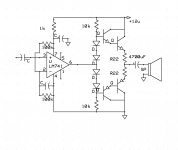
Ive tired to construct simple around 3W at 4R amp for my car tweeters that has minimal crossover distortion... As low as possible I think.
My source is quite good CD player but its amplifier is class B and sounds horrible.
I know there's quite few nice sounding chipamps that can run off 12V battery but theres something they all suck at.
I will go for very simple output stage but I have no idea why doesnt it work.
It can be heard at high volume but it distorts the hell out of itself.
Any ideas how could I make it better? That 4700 is overkill for tweeters for sure")
My source is quite good CD player but its amplifier is class B and sounds horrible.
I know there's quite few nice sounding chipamps that can run off 12V battery but theres something they all suck at.
I will go for very simple output stage but I have no idea why doesnt it work.
It can be heard at high volume but it distorts the hell out of itself.
Any ideas how could I make it better? That 4700 is overkill for tweeters for sure
Attachments
Last edited:
You may need to lower the 10k's to increase the Bias of the transistors so that you don't have any crossover distortion.
If the output device are getting warm than you have to decrease the 10k's to lower there idling current.
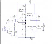
The biggest flaw I see in the schematic is that you have no Feedback resistor.
This will cause the circuit to have way too much gain and distort!!
Here is a version I have made (if you haven't seen it yet) and it works perfectly and sounds very nice.
jer
P.S. I have also had set this up for use on a single ended supply as well, I don't have the schematic for that configuration right now, but it is the reason for the extra resistors I had on the input to the opamp, as I drew this as it was on my protoboard before I cleared it off for some thing else.
If the output device are getting warm than you have to decrease the 10k's to lower there idling current.
The biggest flaw I see in the schematic is that you have no Feedback resistor.
This will cause the circuit to have way too much gain and distort!!
Here is a version I have made (if you haven't seen it yet) and it works perfectly and sounds very nice.
jer
P.S. I have also had set this up for use on a single ended supply as well, I don't have the schematic for that configuration right now, but it is the reason for the extra resistors I had on the input to the opamp, as I drew this as it was on my protoboard before I cleared it off for some thing else.
Attachments
Last edited:
You might not be hearing crossover distortion - on chip amps this is still rather low, the HF distortion tends to be input stage dominated. Rather you are probably hearing your noisy supply rails - the solution is way better decoupling. Use handfuls of 10uF 1206 ceramics.
Btw your schematic shows only two diodes to bias one (darlington+resistor), that's considerably underbiassing the output devices. You've also got the 741 running open loop (as geraldfryjr notes) and no DC bias path for its +ve input.
Btw your schematic shows only two diodes to bias one (darlington+resistor), that's considerably underbiassing the output devices. You've also got the 741 running open loop (as geraldfryjr notes) and no DC bias path for its +ve input.
I guess use a simulator (like LTSpice) to get a handle on the output current requirements of the apamp, I have no experience in that area. Yes you're right, even the resistors are going to give the chip some grief - you could though replace them with current sources which won't much load the IC. You'd also want to have the current sources fed from a decoupled supply to minimize HF feed-through.
<edit> Only the top CS would need decoupling seeing as the -ve rail is already your AC gnd.
<edit> Only the top CS would need decoupling seeing as the -ve rail is already your AC gnd.
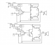
Keep in mind when running on a 12v single ended supply you will only have a output swing as to what the opamp can produce or how close it can get to the rails.
In my circuit I only got about 5v or 6v p-p on 12v.
This may be different when using a Vbe multiplier, I haven't tried that method yet.
jer
In my circuit I only got about 5v or 6v p-p on 12v.
This may be different when using a Vbe multiplier, I haven't tried that method yet.
jer
I didn't have any resistors to use at the time or else I would have used them.
I didn't have it long enough to test for thermal stability much, But as it was I didn't experience any issues.
My plan was to make it on a PCB, Double up the outputs and use a higher current supply and test it further.
As well as trying a HV opamp like the ADA4700-1 or one of the ones from LT such as the LT6090 or LTC2057HV.
Just haven't got that far yet.
jer
- Status
- This old topic is closed. If you want to reopen this topic, contact a moderator using the "Report Post" button.
- Home
- Amplifiers
- Chip Amps
- LME49990 as single supply power amplifier VAS...