Hi All,
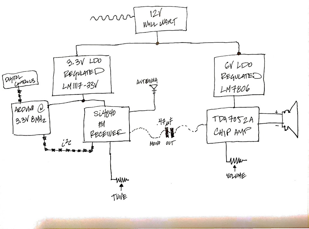
I'm building myself a little FM receiver using the Silicon Labs Si4840 FM-receiver-on-a-chip, and a TDA7052A amplifier. The Si4840 is controlled by an Arduino via i2c.
I've got the circuit assembled on PCB and working, and it sounds pretty good, except that there's a fairly constant high-pitched tone. The tone is present whether the FM receiver is sending it a signal or not, and goes up or down with the volume control on the TDA7052A.
I guess I could put a low-pass filter on the output, but I'd like to understand why this is happening, if only for my own edification-- I've built a few audio circuits, but still don't feel like I have a very good handle on best practices.
Here is the block diagram:
Top view:
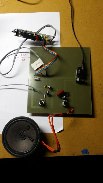
Bottom view:

I've also attached the schematic and board pdfs. Thanks for any help or tips!
I'm building myself a little FM receiver using the Silicon Labs Si4840 FM-receiver-on-a-chip, and a TDA7052A amplifier. The Si4840 is controlled by an Arduino via i2c.
I've got the circuit assembled on PCB and working, and it sounds pretty good, except that there's a fairly constant high-pitched tone. The tone is present whether the FM receiver is sending it a signal or not, and goes up or down with the volume control on the TDA7052A.
I guess I could put a low-pass filter on the output, but I'd like to understand why this is happening, if only for my own edification-- I've built a few audio circuits, but still don't feel like I have a very good handle on best practices.
Here is the block diagram:
Top view:
Bottom view:
I've also attached the schematic and board pdfs. Thanks for any help or tips!
Attachments
Update: I worked on this some more with the oscilloscope to try to figure out where it's coming from. I can't seem to get a lock on the sound with the oscope and upon listening more carefully, it seems like it might just be high-pitched noise, rather than a waveform.
It's louder when I run a signal through the system, and if I disconnect the FM receiver altogether it's at the threshold of hearing.
It's louder when I run a signal through the system, and if I disconnect the FM receiver altogether it's at the threshold of hearing.
I've got bypass capacitors on the Arduino and the Si4840, but I see that I don't have them on the input power to the amplifier :/
We are learning things today, like that the typical application circuit in the datasheet doesn't show everything you need to make the system work!
I'll try adding them and report back.
We are learning things today, like that the typical application circuit in the datasheet doesn't show everything you need to make the system work!
I'll try adding them and report back.

Hmm, I tried adding a low-pass filter at the amp input with a corner frequency of 10KHz, but that had no effect that I can hear.
So that means that the issue isn't in the signal path referenced to ground per se, but rather in the 3V supply to the microprocessor/FM tuner, or the 6V supply to the amp, or the potential between them? Does that seem like a good hypothesis? And if so, how do I fix it?
So that means that the issue isn't in the signal path referenced to ground per se, but rather in the 3V supply to the microprocessor/FM tuner, or the 6V supply to the amp, or the potential between them? Does that seem like a good hypothesis? And if so, how do I fix it?
Last edited:
The smallest value caps should be the closest to the chips as possible if not right on them dead bug style.
Also the noise can be picked up from the large looped traces as well as they are right next to the lines from the MCU with no isolation in between them.
The ground plane is also split up in several sections and this may not be good as well if not implemented correctly.
I you can get a scope it is possible to see exactly which trace is carrying the noise or picking it up.
There have been several threads about these types of discussions and just recently too.
Very interesting and informative!!
The ground plane has to be just certain or else it will pick up more noise rather than keeping everything quiet as it is supposed to do .
Traces should be kept as short as possible as well with no loops if possible, in this case it can be done.
I think I have an idea as to what the sound is like but no amount of audio filtering will eliminate.
It is digital noise and it is most likely seeping from the ground side of things or having the digital traces to close to the analog traces.
Do make sure that you have adequate filter and bypassing on all of your supply's as well.
I read a paper not long ago that no more than two values of caps should be used for bypassing else things can get worse.
I don't have any experience with this type of stuff but I am going to venture into the mixed signal realm very shortly.
However, I have done a lot the reading on the subject and I have watched the other threads here very closely about this.
I once watch a video that showed a simple Mixed signal A/D not working well and very noisy, They went through the various stages of proper bypassing and then the circuit worked exactly perfect as designed.
I will try to find that link for you.
jer")
Also the noise can be picked up from the large looped traces as well as they are right next to the lines from the MCU with no isolation in between them.
The ground plane is also split up in several sections and this may not be good as well if not implemented correctly.
I you can get a scope it is possible to see exactly which trace is carrying the noise or picking it up.
There have been several threads about these types of discussions and just recently too.
Very interesting and informative!!
The ground plane has to be just certain or else it will pick up more noise rather than keeping everything quiet as it is supposed to do .
Traces should be kept as short as possible as well with no loops if possible, in this case it can be done.
I think I have an idea as to what the sound is like but no amount of audio filtering will eliminate.
It is digital noise and it is most likely seeping from the ground side of things or having the digital traces to close to the analog traces.
Do make sure that you have adequate filter and bypassing on all of your supply's as well.
I read a paper not long ago that no more than two values of caps should be used for bypassing else things can get worse.
I don't have any experience with this type of stuff but I am going to venture into the mixed signal realm very shortly.
However, I have done a lot the reading on the subject and I have watched the other threads here very closely about this.
I once watch a video that showed a simple Mixed signal A/D not working well and very noisy, They went through the various stages of proper bypassing and then the circuit worked exactly perfect as designed.
I will try to find that link for you.
jer
I'm not liking the digital pins bleeding into the audio signal theory, for two reasons:
1. Once configuration of the FM receiver IC is complete, there aren't any more digital signals sent (at present)-- the i2c pins just float high. So no switching noise, I wouldn't think.
2. Were that the case, installing a low-pass filter at the amp input would have fixed or at least lessened the problem, but I didn't hear any difference
I guess I can try etching breaks in the groundplane to try to break up possible loops of current, but that just feels like fishing. I've also ordered another speaker, just on the off chance that's the issue -- the one I'm using is salvaged from another piece of equipment.
Nope the speaker is not going to change anything.
If the MCU board is sharing the same supply via separate line, it is possible that a ground loop is being formed by the ground connection at the connection strip on your board.
I had similar issues when I used a PIC on my programmer board to generate a clock for an A/D that is built on a Protoboard.
Noise was getting in to everything causing the A/D to miss codes as LED's were the output.
It made a big difference as to where I took the common ground from for the clock signal from the programmer board.
I don't remember but I think disconnecting the ground wire all together solved the problem and even though they had separate power supply's the signal coming off of the PIC was enough to clock the A/D.
jer
I don't see any bypass cap on the receiver chip Vdd2.
What happens to the noise when you disconnect C4 from the receiver chip and ground it?
If it goes away then the noise is coming from the receiver section and the layout may have to be changed.
Large looped traces are not good and should be avoided if possible.
Notice in the Data sheet and in a picture of this commercial unit the traces are kept very close to the chip and very short as well.
On page 3 and 20 here,
http://www.silabs.com/Support Documents/TechnicalDocs/Si484x-DEMO.pdf
and a picture of the Commercial unit here,
http://3.bp.blogspot.com/-wd8YGeRMm7Y/Uc1iWhueBDI/AAAAAAAABG8/bvyTRRpZcW8/s500/R2010D_internal.jpg
These types of issues are a PITA to decipher!!!
It could even be as simple as putting it in a metal box or it is picking up the MCU via antenna input.
jer
Last edited:
Hey, so an update on this: I redesigned the circuit layout such that trace lengths are minimized, and laid things out on a star ground. Same high pitches white noise, no improvement at all. So, it's not a layout issue.
The only thing that seemed to make any difference was to completely disconnect the input pin on the amp. If there was anything connected to it at all, there's the noise. So I think that narrows it down to:
1. An issue inherent in the circuit design that is independent of the layout of the circuit
2. An issue inherent to the amplifier
Updated circuit design:
Hello, I am starting to make a radio using the Si4844 controlled by an arduino when I ran across this post.
I'm not real big into reinventing the wheel so I wonder if you would be willing to share the arduino software you are using to control the Si4840?
Thank for considering that.
I'm not real big into reinventing the wheel so I wonder if you would be willing to share the arduino software you are using to control the Si4840?
Thank for considering that.
- Status
- This old topic is closed. If you want to reopen this topic, contact a moderator using the "Report Post" button.
- Home
- Amplifiers
- Chip Amps
- High-pitched tone with TDA7052A...need some help here