Let's run through the current version to check how a manual offset trim would be feasible.
Hi Klaus,
your post is invaluable, thanks
")
Some time to digest it is needed...
But we don't have matched input resistances, one leg is 103k (R12+R13) while the other is 12k (R7). That alone could give a lot of current offset.
Input voltage at the 12k leg is 12k*500nA=6mV and input voltage at the 103k leg is 103k*500nA=51.5mV(!!) which results in an additional voltage offset of 45.5mV. And that is with zero offset current spec.
We could reduce R13 to 10k and that would match and lower source resistances as seen by the chip, any remaining offset would be convenient to trim out then. Any preamp (except exotic "passive" pre's with larger than 10k pots) should be happy to drive a 10k load.
..
If it was decided to try to balance input impedance, you could also increase the other leg (R7 + R10), for example, we could use a 100k for R7 and 3.3k for R10 and that would balance impedances. It would also bring C9, if needed, down to 26 uF with the same corner frequency, almost film territory.
Likely, this would be easiest somewhere in between for both legs, as long as they were balanced.
Well, I would think the main question is : do we actually need a servo, other than for a design excersise (which is fine, of course). I mean, did anybody ever have more than 20mV or so of offset?
Since C9 is present no one had, from what I know, more than 10-15mV of offset, most between 5 and 10mV.
So the servo is not necessary but is needed to remove C9.
That cap has a great effect on sound and the best caps in such position, Black Gates, are no longer available.
Also it's a great opportunity to learn something on DC servos.
Regarding your previous, wonderful and informative post... I'll try to summarize, please correct me if I misunderstood:
- the trimmer can deal with LM318's intrinsic DC offset
- the DC offset is dominated by the bias currents generated one and the actual design is pretty unbalanced in this regard
- So C9 or a DC servo is still needed even if we trim LM318's DC offset.
- a 120-150mV pull range for the DC servo should be more than adequate
According Cordell the capacitor in the post filter would be critical for sound quality and the goal is to remove as much as possible this problem.
(...)
Absolutely, but with a so low Fc (0.16Hz) how much AC would pass past the DC Servo? Isn't filtered enough?
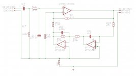
Andrew, one nice thing about the double opamp Cordell's approach is that we can do active post filtering:
Attachments
Last edited:
...Do not "add" an inverting opamp to either the non-inverting or the inverting servo. Just feed into the appropriate feed in node.
...
It can be fitted with an output filter. I consider this last mandatory...
I concur with both of these - it's simple and elegant, minimizes active parts, and can be optimized without too much difficulty.
Of course, the offset trim of the LM318 is even simpler, if there's not much ripple feedthrough from the opamp supply rail to the trim terminals (which are internally connected to the collectors of the LM318 LTP, and very much in the audio path, IIRC).
An interesting experiment
OK, I was curious.
I took one channel of my FE RC amp, disconnected the speaker, shorted the input, and measured the voltage offset at the output. Then, I simply added a jumper wire to bypass the capacitor at C9. If Klaus' description is correct, we should see a jump in DC output offset.
Results
w/o C9 jumper - DC offset = 0.6 mV
with C9 jumper - DC offset = 20 mV
So I think we can say that C9 is killing a significant amount of offset. By the way, the offset was drifting, especially with the jumper. I'm not sure if that advocates for an active DC servo or if the pin 1 and 5 offset trim with a potentiometer would be enough.
I am also curious about the effect of a balanced input impedance. A very interesting design exercise all around.
Jac
I took one channel of my FE RC amp, disconnected the speaker, shorted the input, and measured the voltage offset at the output.
Really interesting Jac.
20mV is not that high, too; there are Gainclones with higher DC-Offset.
BTW we want less than 10mV so C9 or a DC-Servo are still needed.
the removal of the DC blocking capacitor then presents the input transistors with unbalanced source "resistance".
This unbalanced source resistance leads to increased sensitivity to temperatures effects and thus drifting with temperature.
Fortunately the input transistors inside the opamp will have a slow temperature error.
A slow acting DC servo will apply adequately fast correction to maintain a lowish to very low output offset.
there are many badly designed or badly assembled chipamp power amplifiers, where the builder/designer forgets that +-2mVdc is an achievable offset target without any special procedures..............20mV is not that high, too; there are Gainclones with higher DC-Offset...............
Lehman confirms with this result:
w/o C9 jumper - DC offset = 0.6 mV
Hello,
first of all, let me thank Dario and all the people involved in this thread: to add a DC servo to the My_ref FE is another excellent idea!
About the input impedances at the LM318, you all may remember that every component in the Mauro's design is carefully thought and I do think that the "unbalance" in the input impedances was made on purpose.
Second, still someone is writing about a change of the LM318. Again, please remember that the My_ref amplifier is a very sophisticated design where there is a strong use of feedback concept, phases balance, etc and that most concepts are tuned around the LM318. Change op-amp would mean to change almost all the components values, at least.
Third, the my_ref evolution had a DC servo (I'm sure that all of you know this). A simplified scheme was published on "costruire Hifi" n.116 (an Italian Hifi DIY magazine). I wonder if it is possible to publish here just the scheme. Dario, what do you think? It may help a lot.
my three cents,
Daniele
I did not know any of this..................the my_ref evolution had a DC servo (I'm sure that all of you know this). A simplified scheme was published ..................
Mauro chose not to detail any of the evolution to DIYaudio Members.
Ask Mauro for permission and then post data............... I wonder if it is possible to publish here just the scheme............
About the input impedances at the LM318, you all may remember that every component in the Mauro's design is carefully thought and I do think that the "unbalance" in the input impedances was made on purpose.
Daniele
Daniele,
I agree that Mauro is extremely expert and creative in his solutions and that the "unbalance" may be a design decision. I also think that we shouldn't treat his design as untouchable. If nothing else, I can learn something about the difference between theory and reality by trying some new ideas, and learning from my mistakes. If we play with these ideas as a design exercise, we may even understand some of the reasons why Mauro chose what he chose, since he is not here to answer questions.
With that in mind, I plan to build a pair of FE RC boards with balanced input impedance. I can't say when I will do this, but it is now on the project list. My idea is to balance impedance by changing R7 and R10 and that will drive changes to C9, C10, and C32. Theory suggests that I should be able to do this without changing stability or audio quality, but I am not at all sure of the result. I have more simulation and more study on how the compensation works before I select values and components. In the end, I hope to discover if the balance reduces/eliminates the need for C9.
I see this as a parallel approach to the DC servo investigation based on learning from Klaus' comments. I will let you know if I learn something.
Jac
I've taken my proper place as an observer to this project as y'all are way beyond my understanding. However, I have noticed the word "balanced" appearing often. Since this will most likely lead to a new PCB anyway, is there any merit to considering full balanced operation in the new design?
As Daniele notes, implementation of some suggested modifications would result in something that's not strictly a MyRef as envisioned by Mauro. I do know just enough to understand "balanced" as used in the past few posts is not the same as a balanced system signal path. I've also been following developments here on the forum where John Curl is participating in a conversion of his highly regarded JC-2 preamp from SE to a new balanced design.
So I'm just throwing out the possibility that this thread might lead to something that is neither a modified MyRef nor an Evolution - possibly a group designed new amp that captures and builds upon the strengths of Mauro's work while featuring some essential departures that could prove beneficial.
?????????
EDIT: Wow Jac - I was writing as you were posting. Must be something worth following - (or at least interesting)
Last edited:
http://www.diyaudio.com/forums/soli...sed-lme49830-lateral-mosfets.html#post2717072
it is the 49830 opc used.
it is the 49830 opc used.

That could well be. Maybe he found empirically for LM318 (with the parts he had) that unbalancing source resistances leads to some cancelling of offset contributing mechanisms, that is, cancelling a systematic voltage offset with a proper selection of current-induced offset and by lucky chance it happened to be that the DC resistance at the -IN needs to be higher for this than at the +IN (well, maybe it just happened this way, he consistently saw little offset, then let's keep it this way in spite of the imbalance he was surely aware of).About the input impedances at the LM318, you all may remember that every component in the Mauro's design is carefully thought and I do think that the "unbalance" in the input impedances was made on purpose.
Jac's measurement at least provides one positive data point for this scenario. Of course there is no guarantee that every single LM318 would show this behaviour, especially accross different manufacturers (NS/LT/UTC etc) and/or silicon processes used (it's a very old design after all, the original wafer technologies are long gone since).
- Status
- This old topic is closed. If you want to reopen this topic, contact a moderator using the "Report Post" button.
- Home
- Amplifiers
- Chip Amps
- My_Ref Fremen Edition - Collaborative DC-Servo design