While it was planned I never introduced a DC servo in the FE since my electronic knowledge is pretty basic and designing a good sounding/performing DC servo is not a trivial task and I wanted first to have a good sounding/performing new amp as a base.
My_Ref FE Schematic
Black Gates for C9 position of the My_Ref and its variants, like my Fremen Edition, are good enough to mitigate the need for a DC servo but they are every day more difficult to source and prices are rising sky-high.
Now I think it's time to give the My_Ref a DC servo to eliminate such cap but I need help from more prepared forumers, like AndrewT, KSTR, Gotee or whoever is willing to help/teach us a pratical approach to its design.
In the last days I've had an interesting and useful mail exchange with Siva who is willing to contribute to this thread (in fact he already started contributing via mail") )
)
Design goals are good performance, simplicity and a as lower as possible parts count since there's no much space on the PCB.
The first thing to define is where the DC servo has to be inserted in a nested design like this.
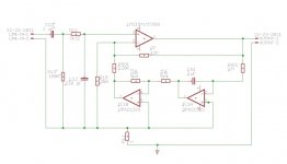
IMHO it's not too difficult if we 'model' the LM318 and LM3886 as a single power opamp, like in this simplified schematic:

The model opamp is used in a non inverting topology since both stages (LM318 and LM3386) are inverting, so the combined amp is non inverting.
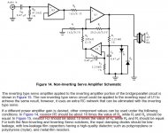
The next step is to add a simple, basic DC servo like the one used in AN-1192 (Figure 14):
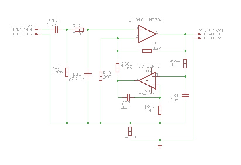
If I've undestood correctly the RSI1/CS1 combo is a LP filter with 0.16 cutoff freq. (AN-1192 circuit used 2.21M and 0.47uf with fc=0.15Hz) so that the integrator deal only with near DC signal.
The RSO1 resistor, from what I've read, is usually set 10x the feedback resistor of the amp so to lower noise and AC injection to the main amp.
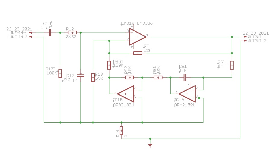
Another approach could be Bob Cordell one's (from his book Designing Audio Power Amplifiers) which uses a single inverting integrator, so to use a single high quality cap, followed by an inverting unity gain integrator to have a non inverting DC-Servo.
I've, at leat initially, excluded post DC-Servo filtering since the shunt cap would be another critical (soudwise) part, not less important than the original C9.
If a good enough circuit will be defined I'll need some beta testers to build the amp and possibly test it for stability and objective performance with measuring/diagnostic equipment, subjective testers are obviously welcome too.
Any feedback/suggestion/contribution/revision is welcome.
My_Ref FE Schematic
Black Gates for C9 position of the My_Ref and its variants, like my Fremen Edition, are good enough to mitigate the need for a DC servo but they are every day more difficult to source and prices are rising sky-high.
Now I think it's time to give the My_Ref a DC servo to eliminate such cap but I need help from more prepared forumers, like AndrewT, KSTR, Gotee or whoever is willing to help/teach us a pratical approach to its design.
In the last days I've had an interesting and useful mail exchange with Siva who is willing to contribute to this thread (in fact he already started contributing via mail
)Design goals are good performance, simplicity and a as lower as possible parts count since there's no much space on the PCB.
The first thing to define is where the DC servo has to be inserted in a nested design like this.
IMHO it's not too difficult if we 'model' the LM318 and LM3886 as a single power opamp, like in this simplified schematic:
The model opamp is used in a non inverting topology since both stages (LM318 and LM3386) are inverting, so the combined amp is non inverting.
The next step is to add a simple, basic DC servo like the one used in AN-1192 (Figure 14):
If I've undestood correctly the RSI1/CS1 combo is a LP filter with 0.16 cutoff freq. (AN-1192 circuit used 2.21M and 0.47uf with fc=0.15Hz) so that the integrator deal only with near DC signal.
The RSO1 resistor, from what I've read, is usually set 10x the feedback resistor of the amp so to lower noise and AC injection to the main amp.
Another approach could be Bob Cordell one's (from his book Designing Audio Power Amplifiers) which uses a single inverting integrator, so to use a single high quality cap, followed by an inverting unity gain integrator to have a non inverting DC-Servo.
I've, at leat initially, excluded post DC-Servo filtering since the shunt cap would be another critical (soudwise) part, not less important than the original C9.
If a good enough circuit will be defined I'll need some beta testers to build the amp and possibly test it for stability and objective performance with measuring/diagnostic equipment, subjective testers are obviously welcome too.
Any feedback/suggestion/contribution/revision is welcome.
Attachments
Last edited:
Are you thinking about a module that attaches to the current board or a new PCB?
All is possible but I've thinking more about new PCBs, I don't know if it would be stable with a piggy back module.

All is possible but I've thinking more about new PCBs, I don't know if it would be stable with a piggy back module.
Dario,
You and Siva have already given this a fair bit of thought. I am pretty sure that I don't know enough to contribute much, but am willing to help where I can. I also would like to support as a beta tester and will work on how I could test stability. I have some measurement tools, not as good as others, and not enough experience to address the best way to test. I will put my focus to learning about how to test.
Although your idea of a new board is probably the right one, please keep open the idea of a daughter board as it gives existing boards an option.
Ironically, I am planning to try a few alternatives to C9, including the BG NX, Tom's Jensen's, and the low cost Mundorf M-Cap AC. That should make a nice contrast to the DC Servo question.
Jac
One other question to think about. R7 has compensation in the form of C32 and possible affects from C10. How do those function and how would a DC Servo working in parallel interact with them? This may be where simulation will help, but I am hoping that an expert has a good theoretical understanding and can help explain.
Hi Jac,
Thanks, your support is welcome and appreciated
Before beta PCBs I'll try circuits on veroboards but at the moment I can't be sure about stability but the possibility is open.
I don't think previous builders will need to upgrade to new boards.
Really, this DC-servo project is to keep the FE future proof, a BG NX in C9 could even be better sounding than the DC-Servo...
Absolutely, this thread will try to address these questions too.
I am pretty sure that I don't know enough to contribute much, but am willing to help where I can. I also would like to support as a beta tester and will work on how I could test stability.
Thanks, your support is welcome and appreciated
Although your idea of a new board is probably the right one, please keep open the idea of a daughter board as it gives existing boards an option.
Before beta PCBs I'll try circuits on veroboards but at the moment I can't be sure about stability but the possibility is open.
Ironically, I am planning to try a few alternatives to C9, including the BG NX, Tom's Jensen's, and the low cost Mundorf M-Cap AC. That should make a nice contrast to the DC Servo question.
I don't think previous builders will need to upgrade to new boards.
Really, this DC-servo project is to keep the FE future proof, a BG NX in C9 could even be better sounding than the DC-Servo...
R7 has compensation in the form of C32 and possible affects from C10. How do those function and how would a DC Servo working in parallel interact with them? This may be where simulation will help, but I am hoping that an expert has a good theoretical understanding and can help explain.
Absolutely, this thread will try to address these questions too.
In the last days I've had an interesting and useful mail exchange with Siva who is willing to contribute to this thread (in fact he already started contributing via mail
...
The model opamp is used in a non inverting topology since both stages (LM318 and LM3386) are inverting, so the combined amp is non inverting.
The next step is to add a simple, basic DC servo like the one used in AN-1192 (Figure 14):
Thanks, Dario. To summarize the initial findings:
1) It's possible to inject the correction signal either at the input node or the feedback node (with appropriate changes to the servo polarity). Both topologies are in use in the real world. The AN-1192 circuit (as well as most of the discussion from Gootee on the earlier thread here) injects into the feedback node. The Evolution injects into the input node.
I'm inclined to go with the feedback injection topology, since it simplifies several things. However, since the feedback node has a low impedance to ground (390 || 12k), the pull range of the servo will be fairly small unless a lot of current is injected into the node.
2) As a quick back-of-the envelope calculation, +/- 1 mA gives a pull range of 1 mA times 390 R, or ~390 mV at the feedback node. This seems adequate to correct about +/- 12V at the output. To get +/- 1 mA injection current at +/- 10V swings at the output of the DC servo, we need a series injection resistor (RS01) of about 10k.
3) The Servo has an easier job if the input to the LM318 is AC coupled as shown above - it then only has to correct the offsets introduced by the opamp and chipamp, which are only in the range of 10s of mV. In that case, RS01 can be increased - maybe to somewhere in the 47k to 100k+ region.
4) It seems prudent to to split RS01 into an RCR Low-pass filter T-section, with the C grounded. For instance, if RS01 is ~10k, something like 1k-3.3uF-10k seems to work well in the preliminary simulation (LTSpice seems to have an easier job in converging when this LPF is used, as compared to just using a plain R).
I've, at leat initially, excluded post DC-Servo filtering since the shunt cap would be another critical (soudwise) part, not less important than the original C9.
The C is significantly smaller, allowing the use of something like a Wima MKS2XL in the 470nF to 3.3uF range, which is more linear than a BG-PK 220uF. There's also an element of isolation in the form of the second R in the RCR section - if that's > 10k, the contribution of the C to the sonics of the feedback network will be mostly negligible and inaudible.
Last edited:
Siva,
Very interesting. A lot to think about. I'm out today, but will post what I think is a slightly different version that I found on the internet.
On the subject of the effects of C32, I am coming to the conclusion that the DC Servo will have very little interaction. Please correct me if I am wrong, but it seems that C32 is a bandwidth limiter, that is, at very high frequencies, C32 easily passes current and that reduces gain at high frequencies. This is done to limit the amplification of high frequency noise and to improve stability of the loop at frequencies well above the audible range.
Since the DC Servo is designed to only work at and near DC, it will filter itself to a very low level at high frequencies shouldn't interact with C32.
Between the two designs that Dario showed schematics, I am currently liking the Cordell design. A few reasons that may not be valid. The Cordell design would seem to offer a more consistent output impedance because the second opamp is effectively buffering the varying impedance of the first stage. I suspect that a constant and mostly resistive output impedance would inject less phase distortion to the main feedback circuit.
Also, the second stage of the Cordell design could be at a higher gain, if we need more current injected near DC.
Finally, I like that, in the Cordell design, both opamps are closely referenced to ground. I usually try to avoid using Mega Ohm resistors whenever possible because the are noisy and can pick up RF noise too. The idea that the AN-1192 circuit seems to be isolated between 2 one Meg resistors looks like an opportunity for noise to sneak into the system. Also, any mismatch between the 1 Meg resistors or the caps would show up as an offset voltage at the opamp inputs, wouldn't it? That would make input offset current and quiescent current of the opamp extremely critical, if I am understanding this correctly. I think that the Cordell design would be less sensitive to opamp specs and would probably put it's emphasis on input offset voltage.
Just some thoughts from a very non-expert. Please react with other viewpoints.
Why not try the easy things first? LM318 has offset balancing pins (pin 1&5) that have not been used in the design so far. Part count is minmal, one 100k trimpot to positive supply.
Hi Klaus,
interesting and easy, never though about it!
With my limited knowledge I've had the impression it was a somewhat dynamic behaviour of the input transistors biasing...So it's possible to remove C9 from the circuit simply trimming the DC offset?
That sort of correction will work well also with an applied signal?
Will be stable with temperature?
Klaus,
This is why we love to hear from you. You keep us thinking. And the first thought is to read the LM318 datasheet again, which I should have done already. As you point out, there is offset balancing designed into pins 1 and 5 and they even show a circuit for balancing offset. Assuming that DC offset is fairly constant, it looks like it could work.
If an automatic offset balancing is desired or necessary, it seems like using pins 1 and 5 would be worth considering instead of feedback.
Thanks again.
Jac
Hi Klaus,
interesting and easy, never though about it!
With my limited knowledge I've had the impression it was a somewhat dynamic behaviour of the input transistors biasing...So it's possible to remove C9 from the circuit simply trimming the DC offset?
That sort of correction will work well also with an applied signal?
Will be stable with temperature?
Of course, I hope Klaus answers with his usual expertise, but in the meantime, it seems like something that should be easy to test. At one point, I had the impression that output DC offset was due to a combination of internal offset from the ICs and mis-matching of external components that caused an imbalance. Maybe I was thinking that was why one build had 0.5 mV offset with the input shorted and another build had 5 mV offset. If that were the case, then it seems like trimming might work.
Would it be possible to jumper C9, measure the DC across a dummy load with shorted input, a single frequency, say 1 kHz sine, and white noise to see if the DC measurement changes? For temperature, a heat lamp or hot air gun could make 10 deg C change and help understand the temperature sensitivity of the amp. Note the datasheet shows some offset slope with temperature, but it is very small. Of course, that is only the LM318 and we need to consider the whole amp.
the feed in resistor can be from ~1times R10 value to 20times R10 value.The RSO1 resistor, from what I've read, is usually set 10x the feedback resistor of the amp so to lower noise and AC injection to the main amp.
You referenced R7 instead.
Linux agrees
2) As a quick back-of-the envelope calculation, +/- 1 mA gives a pull range of 1 mA times 390 R, or ~390 mV at the feedback node. This seems adequate to correct about +/- 12V at the output. To get +/- 1 mA injection current at +/- 10V swings at the output of the DC servo, we need a series injection resistor (RS01) of about 10k.
If you want to save resources and space then you must use the inverting DC servo topology.
Do not "add" an inverting opamp to either the non-inverting or the inverting servo. Just feed into the appropriate feed in node.
I much prefer the non-inverting.
THREE reasons.
It has an input filter. this gives the servo amplifier less work to do.
It has a separate integrating capacitor and this dedicated cap gets on and does it's sole job without interference
It can be fitted with an output filter. I consider this last mandatory (see next comment)
These three factors result in less noise and less distortion and less audio, being injected into the feed in node.
Once you add anything to that node it cannot then be removed. It comes out of the speaker output.
Last edited:
Add on a window comparator, that identifies excessive DC servo correction signal.
This is equivalent to DC protection and could activate the protection relay BEFORE the output rail goes to supply rail and welds the relay contacts together.
The protection relay should output a signal to drive a "warning LED".
This is equivalent to DC protection and could activate the protection relay BEFORE the output rail goes to supply rail and welds the relay contacts together.
The protection relay should output a signal to drive a "warning LED".
Let's run through the current version to check how a manual offset trim would be feasible.
First, it's important to note that only the LM318 is contributing, the LM3886 is inside it's feedback loop.
LM318 max offset spec is 10mV (voltage) and 200nA (current). Bias current max spec is 500nA. LM218 would be significantly better both in max and typical specs (but only available in metal can or cerdip, probably harder to get and at a price).
DC gain is unity, so the voltage offset comes in as is 10mV. A non-issue.
Problem is the offset current, which means bias currents of inputs are matched only to this point. If the matching were perfect (zero offset current) *AND* DC input resistances were equal, no offset would result.
But we don't have matched input resistances, one leg is 103k (R12+R13) while the other is 12k (R7). That alone could give a lot of current offset.
Input voltage at the 12k leg is 12k*500nA=6mV and input voltage at the 103k leg is 103k*500nA=51.5mV(!!) which results in an additional voltage offset of 45.5mV. And that is with zero offset current spec.
Actually bias current can be as much as 200nA apart, assuming worst-case that would be in the 12k leg, reducing its offset amount to 3.6mV. The difference would still be dominated by 51.5mV from the higher resistance leg, though.
So, in the current design we could expect a worst-case offset (at 25degC) of about 60mV -- typically it might be only 1/5th of it, say 10mV. Thankfully the gain at DC is 1, so that value doesn't get multiplied.
Now even 60mV wouldn't do any bad to most speakers, only some very high efficiency types with very short excursion might be off-centered by an amount that would be seen in a slightly increased distortion measurement (but not necessarily audible).
To put numbers into perspective, a LM3886 used in datasheet standard config does have similar, or even worse offset, depending again on source resistance mismatch on the input pins, and it will be drifty
If we still want to have the lowest offset that can be had from the LM318, we'd need to a) balance the input resistance and b) make them as low as possible. The chip's offset trims are not intended to be used to null extra offsets from input resistance mismatch and/or too high source resistance. BTW I looked up the wrong figure (sorry), for the offset trim parts and connection see upper left figure on page 7 of the datasheet.
We could reduce R13 to 10k and that would match and lower source resistances as seen by the chip, any remaining offset would be convenient to trim out then. Any preamp (except exotic "passive" pre's with larger than 10k pots) should be happy to drive a 10k load.
We'd need to increase input blocking capacitor (C13) to 10uF to get the same LF input roll-off. Actually 3.3uF of 4.7uF would be enough, still below 1Hz corner frequency. Andrew would certainly make a point with the notion that the input roll-off shouldn't be any lower anyway than the roll-off of the feeback (C9), which currently is at about 2Hz.
Further, matching source impedances also reduced distortion. If we want to get rid of C9 (and C13) as a possible contributor to distortion and use a servo instead, low and matching source impedance would quite wise to have as well for that reason. And making a good servo that doesn't add significant noise and distortion itself isn't trivial either so the net benefit to this circuit is questionable im my view.
As for Andrew's suggestion of using the offset pins of the LM318 to inject a servo signal, yes this can be done (has been done eg to NE5534's) and might be better approach but it's again not exactly trivial.
For general improvement possibilities, one could put the feedback around the relay (see Cordell's book).... and use a better spec'd opamp like OPA627 (no current offset issues), though that's a different amp design, more like the MiniRefs...
Last edited:
Hi Andrew,
first of all, thanks for contributing
I appreciate it.
I'll ask you some deepening on your notes, it's to understand your points, nothing else.
Why should R10 be used instead of R7 (which is the feedback resistor of the composite amp, right?)?
I've simply followed AN-1192:

(excerpt from TI AN-1192)
Can you, please, elaborate?
Not my work, too.
It's Cordell's preferred topology for the DC-Servo:
Figure 8.6 shows a noninverting integrator that requires only one op amp. It is like a single op-amp differential amplifier but with the feedback and shunt resistors replaced with capacitors to make it into an integrator. It requires two capacitors, and this is a disadvantage.
I prefer DC servos that employ a dual op amp and only require a single integrating capacitor, perhaps on the order of 1 mF. It is quite economical to employ a high-quality 1-mF film capacitor. Dual op amps that are of high quality are also relatively inexpensive.
(excerpt from Bob Cordell's Designing Audio Power Amplifiers Book)
I agree but the third point has some problems too.
According Cordell the capacitor in the post filter would be critical for sound quality and the goal is to remove as much as possible this problem.
Absolutely, but with a so low Fc (0.16Hz) how much AC would pass past the DC Servo? Isn't filtered enough?
Sincerely I don't know but I suspect it would be a not trivial task...
It seems pretty interesting but way out of my design capabilities...sadly.
first of all, thanks for contributing
I appreciate it.
I'll ask you some deepening on your notes, it's to understand your points, nothing else.
the feed in resistor can be from ~1times R10 value to 20times R10 value.
You referenced R7 instead.
Why should R10 be used instead of R7 (which is the feedback resistor of the composite amp, right?)?
I've simply followed AN-1192:
(excerpt from TI AN-1192)
Can you, please, elaborate?
Do not "add" an inverting opamp to either the non-inverting or the inverting servo. Just feed into the appropriate feed in node.
Not my work, too.
It's Cordell's preferred topology for the DC-Servo:
Figure 8.6 shows a noninverting integrator that requires only one op amp. It is like a single op-amp differential amplifier but with the feedback and shunt resistors replaced with capacitors to make it into an integrator. It requires two capacitors, and this is a disadvantage.
I prefer DC servos that employ a dual op amp and only require a single integrating capacitor, perhaps on the order of 1 mF. It is quite economical to employ a high-quality 1-mF film capacitor. Dual op amps that are of high quality are also relatively inexpensive.
(excerpt from Bob Cordell's Designing Audio Power Amplifiers Book)
I much prefer the non-inverting.
THREE reasons.
It has an input filter. this gives the servo amplifier less work to do.
It has a separate integrating capacitor and this dedicated cap gets on and does it's sole job without interference
It can be fitted with an output filter. I consider this last mandatory (see next comment)
I agree but the third point has some problems too.
According Cordell the capacitor in the post filter would be critical for sound quality and the goal is to remove as much as possible this problem.
These three factors result in less noise and less distortion and less audio, being injected into the feed in node.
Once you add anything to that node it cannot then be removed. It comes out of the speaker output.
Absolutely, but with a so low Fc (0.16Hz) how much AC would pass past the DC Servo? Isn't filtered enough?
What about the comp pins of the 318?
Can these be used for injecting a servo signal?
Sincerely I don't know but I suspect it would be a not trivial task...
Add on a window comparator, that identifies excessive DC servo correction signal.
This is equivalent to DC protection and could activate the protection relay BEFORE the output rail goes to supply rail and welds the relay contacts together.
It seems pretty interesting but way out of my design capabilities...sadly.
Attachments
- Status
- This old topic is closed. If you want to reopen this topic, contact a moderator using the "Report Post" button.
- Home
- Amplifiers
- Chip Amps
- My_Ref Fremen Edition - Collaborative DC-Servo design