I hope someone might be able to help me here. I have built a 3886 amp using these kits.
Quality LM3886 based mono amplifier DIY KIT Audiophile | eBay
With no input or speakers connected one board gives < 0.003VDC and 0VAC at the speaker terminals. The other gives <0.003VDC but fluctuates between 0 and 40VAC. They share the PS board which gives +37 0 -37 as it should.
All solder joints appear OK, and there are no obvious blown components.
Any idea what is wrong, or where to start looking. I have basic soldering skills, can use a multimeter but can't do much beyond that.
TIA
Can you get help from a friend/colleague/student who has access to an oscilloscope?
I thought this seller had a schematic on his site.
But it's not attached to your link.
Ask the seller for a schematic.
Ask the seller for help.
He sold you a KIT, that requires that HE provides Customer Service.
I thought this seller had a schematic on his site.
But it's not attached to your link.
Ask the seller for a schematic.
Ask the seller for help.
He sold you a KIT, that requires that HE provides Customer Service.
Last edited:
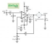
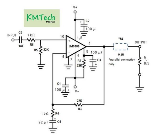
Yes, that's the schematic I saw a few days ago.
It is missing RF attenuation and missing the HF decoupling and missing the Output Zobel
All of these could allow just sufficient instability that would promote oscillation.
There is room on the PCB to add those missing components, if oscillation proves to be the problem.
Oh,
try to find a affordable DMM that has voltage scales that go down to 199.9Vdc and 199.9Vac.
These are very useful to general debugging.
Build up a couple of dummy input plugs for your RCA input sockets.
The first two should have a zero ohms link across Hot/signal to Ground/return/barrel.
Use these when measuring your amplifiers.
Build up a Mains bulb tester. Use it to power up every new project and every start up of a modified project.
I shorted the input and the voltage dropped to 0VAC
When I removed the short, it rose to a stable 1.5VAC
Turning the amp off and on again initially it was ~40VAC which quickly dropped to a stable 1.5VAC without the input shorted. Shorting the input gave 0VAC as before.
My DMM lowest ranges are 20VDC and 200VAC
When I removed the short, it rose to a stable 1.5VAC
Turning the amp off and on again initially it was ~40VAC which quickly dropped to a stable 1.5VAC without the input shorted. Shorting the input gave 0VAC as before.
My DMM lowest ranges are 20VDC and 200VAC
Attachments
get a more sensitive DMM
Don't bother with all the extra facilities.
Build that Mains bulb tester.
An open input behaves like a radio aerial.
The amplifier tries to amplifier all the RF that gets in.
That's why the RF attenuator on the input is required.
The Zobel helps by taking some of the HF that gets past the input filter to audio ground.
The HF decoupling helps by keeping the supply rails more interference free when the amplifier tries to amplify the RF that gets past the input filter.
Read the datasheet and work out what all these missing extras do and where they should be fitted.
They will fit the PCB.
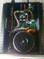
remove the plaited wiring and replace with twisted pairs, or triplets for the +-& zero power.
twist all the other untwisted pairs. They are generating RF interference.
Don't bother with all the extra facilities.
Build that Mains bulb tester.
An open input behaves like a radio aerial.
The amplifier tries to amplifier all the RF that gets in.
That's why the RF attenuator on the input is required.
The Zobel helps by taking some of the HF that gets past the input filter to audio ground.
The HF decoupling helps by keeping the supply rails more interference free when the amplifier tries to amplify the RF that gets past the input filter.
Read the datasheet and work out what all these missing extras do and where they should be fitted.
They will fit the PCB.
remove the plaited wiring and replace with twisted pairs, or triplets for the +-& zero power.
twist all the other untwisted pairs. They are generating RF interference.
Last edited:
<snip>
try to find a affordable DMM that has voltage scales that go down to 199.9Vdc and 199.9Vac.</snip>
<snip>
My DMM lowest ranges are 20VDC and 200VAC
Also why is only one channel affected if its a RF issue?
Last edited:
Originally Posted by AndrewT View Post
<snip>
try to find a affordable DMM that has voltage scales that go down to 199.9Vdc and 199.9Vac.</snip>
Oh bother !!Quote:
Originally Posted by Mr Onion View Post
<snip>
My DMM lowest ranges are 20VDC and 200VAC
I am getting worse.
I meant to type 199.9mVac and 199.9mVdc
milli-volts, not volts.
I shorted the input and the voltage dropped to 0VAC
When I removed the short, it rose to a stable 1.5VAC
Turning the amp off and on again initially it was ~40VAC which quickly dropped to a stable 1.5VAC without the input shorted. Shorting the input gave 0VAC as before.
My DMM lowest ranges are 20VDC and 200VAC
the input cap should have a 100k to ground connected...
another option is a 50k pot to connect that input cap to,
that way you can mute the amp at turn on...
the other hum issue you are having can be due to layout and wiring....
this is how i did my gainclone...

- Status
- This old topic is closed. If you want to reopen this topic, contact a moderator using the "Report Post" button.
- Home
- Amplifiers
- Chip Amps
- Help with LM3886 amp