Hi everyone,
I had some issues a couple of weeks ago with wiring a torroid for a dual mono Chipamp.com LM3886 kit. I've gotten it working now, but I'm having some issues with hum. With open inputs, its dead silent. When I plug in my tester (mobile phone) it starts humming quite loud. It calms down significantly after I hit play, but the hum can still be heard at low volumes. In addition, the chips get quite hot (uncomfortable to touch for more than 10 sec) inside a minute or so if I leave it plugged in to the phone without music playing (while it's humming at the greater volume). If I play music, they still get pretty warm, warmer than I would expect, at a volume that would be comfortable sitting at a desk (not aggressively loud). When I turn the switch to the off position, the caps still have some charge and it'll play for another 2 or 3 sec, with no hum at all.
With music playing, DC offset at terminals was: ~30mv on each channel
Paused the music but still connected (loud hum situation):3.4V left, 300mv right WOW
with open inputs: ~100mv each
shorted inputs to ground:<30mV each. One side was near zero, other was ~30 but I don't remember which was which.
Any ideas? Good thing I'm using junk test speakers.
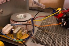
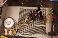
Here are some pictures of the test bed I have made for it with an old receiver chassis and the amp and PS schematics. If anyone is confused about the wiring I can draw up a quick diagram. The ugly board is a soft starter I build off of Rod Elliots design. Excuse the **** poor soldering and layout, it's the first thing I ever soldered.
I had some issues a couple of weeks ago with wiring a torroid for a dual mono Chipamp.com LM3886 kit. I've gotten it working now, but I'm having some issues with hum. With open inputs, its dead silent. When I plug in my tester (mobile phone) it starts humming quite loud. It calms down significantly after I hit play, but the hum can still be heard at low volumes. In addition, the chips get quite hot (uncomfortable to touch for more than 10 sec) inside a minute or so if I leave it plugged in to the phone without music playing (while it's humming at the greater volume). If I play music, they still get pretty warm, warmer than I would expect, at a volume that would be comfortable sitting at a desk (not aggressively loud). When I turn the switch to the off position, the caps still have some charge and it'll play for another 2 or 3 sec, with no hum at all.
With music playing, DC offset at terminals was: ~30mv on each channel
Paused the music but still connected (loud hum situation):3.4V left, 300mv right WOW
with open inputs: ~100mv each
shorted inputs to ground:<30mV each. One side was near zero, other was ~30 but I don't remember which was which.
Any ideas? Good thing I'm using junk test speakers.
Here are some pictures of the test bed I have made for it with an old receiver chassis and the amp and PS schematics. If anyone is confused about the wiring I can draw up a quick diagram. The ugly board is a soft starter I build off of Rod Elliots design. Excuse the **** poor soldering and layout, it's the first thing I ever soldered.
Attachments

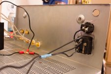
It looks like you have a switch in the N from the power entry.
A switched N still leaves live power on transformer primary...not good idea.
It should be: power---fuse---switch---transformers.(heat shrink over all connections including power entry module and switch)
Good that GND goes to chassis but try to find some green or green/yellow wire for GND.
As for your noise issue...try bundling the AC feed from transformers to rectifier board...minimizing loop areas.
Change the sig-in feed to the amps to some kind of co-axial cable.
")
A switched N still leaves live power on transformer primary...not good idea.
It should be: power---fuse---switch---transformers.(heat shrink over all connections including power entry module and switch)
Good that GND goes to chassis but try to find some green or green/yellow wire for GND.
As for your noise issue...try bundling the AC feed from transformers to rectifier board...minimizing loop areas.
Change the sig-in feed to the amps to some kind of co-axial cable.
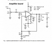
You have the minimalist schematic.
All the National declared "optional" compnents have been omitted.
Add two input filters. A High Pass to block DC and filter sub audio. A low pass to attenuate Radio Frequency (RF).
Make the HF decoupling route as short as possible. The junction between them is the Power Ground, to which you terminate the MF decoupling.
Make the Zobel route as short as possible from Output Pin to Power Ground.
Add an output R||L to convert the Output Zobel to a Thiele Network. This goes into the cable route from chipamp PCB to Chassis mounted Spkr terminals. Twist this cable before and again after the R||L, right up to the terminals.
Connect Ci to R2 and that to input signal return. Make sure that signal return actually returns to the Signal Input socket (or to the base of the vol pt if you have it inside the Power Amplifier).
What cap type have you used fore Cs?
What have you fitted across the rectifier?
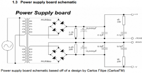
Have you fitted the 0.1uF shown on Carlos' PSU schematic? Remove it.
Twist every pair of Flow and Return cables. Mains cables, Power Supply cables, Signal cables, Speaker cables, transformer secondary cables, rectifier cables. If the power supply becomes a +ve & -ve and Zero volts, then this becomes a twisted triplet, but it looks like your rectified power is all done on the PCB. What happens between the PSU PCB and the Chipamp PCB?
The only exception to this twisted pair is the PE wire. It is a solitary wire.
All the National declared "optional" compnents have been omitted.
Add two input filters. A High Pass to block DC and filter sub audio. A low pass to attenuate Radio Frequency (RF).
Make the HF decoupling route as short as possible. The junction between them is the Power Ground, to which you terminate the MF decoupling.
Make the Zobel route as short as possible from Output Pin to Power Ground.
Add an output R||L to convert the Output Zobel to a Thiele Network. This goes into the cable route from chipamp PCB to Chassis mounted Spkr terminals. Twist this cable before and again after the R||L, right up to the terminals.
Connect Ci to R2 and that to input signal return. Make sure that signal return actually returns to the Signal Input socket (or to the base of the vol pt if you have it inside the Power Amplifier).
What cap type have you used fore Cs?
What have you fitted across the rectifier?
Have you fitted the 0.1uF shown on Carlos' PSU schematic? Remove it.
Twist every pair of Flow and Return cables. Mains cables, Power Supply cables, Signal cables, Speaker cables, transformer secondary cables, rectifier cables. If the power supply becomes a +ve & -ve and Zero volts, then this becomes a twisted triplet, but it looks like your rectified power is all done on the PCB. What happens between the PSU PCB and the Chipamp PCB?
The only exception to this twisted pair is the PE wire. It is a solitary wire.
Last edited:
Shorten the Protective Earth (PE) wire and bolt it next to the mains cable entry hole.
This Safety Earth is permanent and should never be dismantled.
Is Green/yellow sleeving available in the USA?
But ONLY use it on the PE wire, no where else.
Yes, I seem to remember that there is to be no other connections to the Protective Earth Ground connection point.
I don't know about G/Y sleeving because we use G/Y wire at work.
If anything there is green vinyl marker tape available...or green heatshrink.
Must be past my bedtime ! too many typos. Now corrected.You have the minimalist schematic.
Most of the National declared "optional" components have been omitted.
Add two input filters. A High Pass to block DC and filter sub audio. A low pass to attenuate Radio Frequency (RF).
Make the HF decoupling route as short as possible. The junction between them is the Power Ground, to which you terminate the MF decoupling.
Make the Zobel route as short as possible from Output Pin to Power Ground.
Add an output R||L to convert the Output Zobel to a Thiele Network. This goes into the cable route from chipamp PCB to Chassis mounted Spkr terminals. Twist this cable before and again after the R||L, right up to the terminals.
Connect Ci to R2 and that to input signal return. Make sure that signal return actually returns to the Signal Input socket (or to the base of the vol pot if you have it inside the Power Amplifier). Add a reference wire from Signal Return to Main Audio Ground.
What cap type/s have you used for Cs?
What have you fitted across the rectifier?
Have you fitted the 0.1uF shown on Carlos' PSU schematic? Remove it.
Twist every pair of Flow and Return cables. Mains cables, Power Supply cables, Signal cables, Speaker cables, transformer secondary cables, rectifier cables. If the power supply becomes a +ve & -ve and Zero volts, then this becomes a twisted triplet, but it looks like your rectified power is all done on the PCB. What happens between the PSU PCB and the Chipamp PCB?
The only exception to this twisted pair is the PE wire. It is a solitary wire.
BTW,
a minimalist can be built with a chipamp and just 6 external components.
A typical implementation usually uses from 10 to 14 external components.
I start with a layout that has 41 external components and remove only those that are duplicated else where.
Last edited:
The schematic you have is fine. Don't start adding components arbitrarily until you have figured out why you get hum in your circuit. The schematic as-is will work in 99.9 % of cases. Once you have it working, you can start optimizing. The "optional" components that people refer to were copied from an AC test circuit in the data sheet. They are not required for functionality, but could improve performance under certain conditions. Which conditions and improvements are described in the data sheet.
Anyway. You're building this on a PCB that, presumably, the designer tested before sending to market. It should work. The boards look familiar. Gainclone? Many have built those successfully, so the boards or the circuits are not likely to blame.
I bet one of the input connections is bad. You say the circuit is quiet with the source disconnected. This means that R2 is probably connected. As is the rest of the amp. So my guess is that the fault lies to the left of R2 is the schematic. Check the connections on R1 and the volume pot (if fitted), input connectors, and the cable going to the source. Check both the signal and signal return.
With a battery powered source, you're operating at the best case scenario for ground loops. I.e. the case that is the least likely to result in a ground loop. The fact that the amp is quiet with the source unplugged leads me to believe that the amp is good, but the source connection is bad.
If cleaning up and reflowing the solder joints in the input path doesn't clear things up, try another source just in case it should be a source problem.
Re wire colors: The electrons don't care about the color of the insulation, obviously. But it is mighty handy for the builder if a certain standard is followed. For mains wiring in the US, green is earth/ground, black is hot (marked L for Live), white is neutral (N). In the EU, yellow/green is earth/ground, brown is hot, blue is neutral as I recall.
Earth/ground from the mains inlet MUST connect to the metal chassis. If the chassis is non-conductive, it must connect to all metal parts that can be accessed by the user. That's a safety issue.
In DC circuits, red is commonly used for the positive supply and black for the supply return (minus connection on the battery). I use blue for the negative supply.
If you only have one color of wire, coloring the ends with electrical tape or, preferably, heat shrink works well.
~Tom
Last edited:
It looks like you have a switch in the N from the power entry.
A switched N still leaves live power on transformer primary...not good idea.
It should be: power---fuse---switch---transformers.(heat shrink over all connections including power entry module and switch)
Good that GND goes to chassis but try to find some green or green/yellow wire for GND.
As for your noise issue...try bundling the AC feed from transformers to rectifier board...minimizing loop areas.
Change the sig-in feed to the amps to some kind of co-axial cable.
Maybe I'm an idiot but with AC does it matter which line off the mains I switch? One is always available to bite you if you are grounded correct? You're saying move the switch to the other AC terminal?
Shorten the Protective Earth (PE) wire and bolt it next to the mains cable entry hole.
This Safety Earth is permanent and should never be dismantled.
Is Green/yellow sleeving available in the USA?
But ONLY use it on the PE wire, no where else.
Should I use this as a star ground still? or star ground elsewhere and run wire between SE chassis connection and star?
The schematic you have is fine. Don't start adding components arbitrarily until you have figured out why you get hum in your circuit. The schematic as-is will work in 99.9 % of cases. Once you have it working, you can start optimizing. The "optional" components that people refer to were copied from an AC test circuit in the data sheet. They are not required for functionality, but could improve performance under certain conditions. Which conditions and improvements are described in the data sheet.
Anyway. You're building this on a PCB that, presumably, the designer tested before sending to market. It should work. The boards look familiar. Gainclone? Many have built those successfully, so the boards or the circuits are not likely to blame.
I bet one of the input connections is bad. You say the circuit is quiet with the source disconnected. This means that R2 is probably connected. As is the rest of the amp. So my guess is that the fault lies to the left of R2 is the schematic. Check the connections on R1 and the volume pot (if fitted), input connectors, and the cable going to the source. Check both the signal and signal return.
With a battery powered source, you're operating at the best case scenario for ground loops. I.e. the case that is the least likely to result in a ground loop. The fact that the amp is quiet with the source unplugged leads me to believe that the amp is good, but the source connection is bad.
If cleaning up and reflowing the solder joints in the input path doesn't clear things up, try another source just in case it should be a source problem.
Re wire colors: The electrons don't care about the color of the insulation, obviously. But it is mighty handy for the builder if a certain standard is followed. For mains wiring in the US, green is earth/ground, black is hot (marked L for Live), white is neutral (N). In the EU, yellow/green is earth/ground, brown is hot, blue is neutral as I recall.
Earth/ground from the mains inlet MUST connect to the metal chassis. If the chassis is non-conductive, it must connect to all metal parts that can be accessed by the user. That's a safety issue.
In DC circuits, red is commonly used for the positive supply and black for the supply return (minus connection on the battery). I use blue for the negative supply.
If you only have one color of wire, coloring the ends with electrical tape or, preferably, heat shrink works well.
~Tom
These are BrianGT boards available as a kit from chipamp.com. I would prefer not to add components arbitrarily as others have absolutely used these PCBs without issue with the "minimalist" design so I must have an issue specific to my soldering and layout. I will try a few of these in about an hour and get back to you guys. Thanks for the advice.
Regarding wire color, i'm fairly colorblind and electrons seem to share this ailment. Since I'm moving the ground anyway, I'll use green this time to satisfy those with better eyes among us
You have the minimalist schematic.
All the National declared "optional" compnents have been omitted.
Add two input filters. A High Pass to block DC and filter sub audio. A low pass to attenuate Radio Frequency (RF).
Make the HF decoupling route as short as possible. The junction between them is the Power Ground, to which you terminate the MF decoupling.
Make the Zobel route as short as possible from Output Pin to Power Ground.
Add an output R||L to convert the Output Zobel to a Thiele Network. This goes into the cable route from chipamp PCB to Chassis mounted Spkr terminals. Twist this cable before and again after the R||L, right up to the terminals.
Connect Ci to R2 and that to input signal return. Make sure that signal return actually returns to the Signal Input socket (or to the base of the vol pt if you have it inside the Power Amplifier).
What cap type have you used fore Cs?
What have you fitted across the rectifier?
Have you fitted the 0.1uF shown on Carlos' PSU schematic? Remove it.
Twist every pair of Flow and Return cables. Mains cables, Power Supply cables, Signal cables, Speaker cables, transformer secondary cables, rectifier cables. If the power supply becomes a +ve & -ve and Zero volts, then this becomes a twisted triplet, but it looks like your rectified power is all done on the PCB. What happens between the PSU PCB and the Chipamp PCB?
The only exception to this twisted pair is the PE wire. It is a solitary wire.
Ci was omitted as it was optional. I completely forgot about that decision until just now. Could that be the issue?
There are three 0.1uF caps used in the PSU schematic, which one? and why?
Dug,
you are shown as Canada. May I presume you have adopted the british convention of Grn/Yel for PE?
...
The company where I work has...maybe because we ship to EU, US,etc., maybe it is CSA requirements...I don't know...I am just cct design and board layout guy.
Last edited:
Update:
Hum goes away when either RCA is disconnected (no hum or heat with only 1 RCA connected to input, I'm using a 3.5mm to RCA)
Moved ground closer to mains input, used green wire
Reflowed input solders on the channel that was getting hot. This required removing the heatsink and separating the two channels from each other (physically). Because there was no heatsink I was able to feel the heat generated much better. Only one channel was getting hot (too hot to touch in <5 sec).
SWITCH RCA (black to red, red to black), OTHER chip gets hot. WTF? played around with RCA cables for a while, used 3 different sources, finally figured out my chassis insulated RCA jacks weren't so chassis insulated...I think. I think this solved that problem.
However, both chips still get hot, doesn't seem like either gets hotter than the other but I have the heatsink back on now so it's a little hard to tell. Hum is still there, hasn't changed a bit.
Hum does NOT go away if I removed chassis grounds.
I do not have a pot inline for the time being.
I haven't upgraded to Coax for inputs yet.
Does this help anyone? Thanks for all the help everyone.
forgot to mention, I get slightly different measurements across R2. R1 and R3, using an Ohmmeter, I get what they are supposed to be (1K and 660). For R2, I get 4-8K (unstable) and 16K for each individual channel. What gives? This should be a 22k Ohm resistor but obviously I'm getting flow through somewhere with less resistance. No surprise since it goes to ground....but why are they different?
problem of your circuit, POWER GND (0v) planes
i recomend,
1.do not use two power supply circuits
connect two amplifire circuits to one power supply circuit
*connect (ps V+,amp1 v+,amp2 V+)
*connect (ps V-,amp1 v-,amp2 V-)
*connect (ps PG+,amp1 PG+,amp2 PG+)
*connect (ps PG-,amp1 PG-,amp2 PG-)
2.remove eart wire.
make it simple
i recomend,
1.do not use two power supply circuits
connect two amplifire circuits to one power supply circuit
*connect (ps V+,amp1 v+,amp2 V+)
*connect (ps V-,amp1 v-,amp2 V-)
*connect (ps PG+,amp1 PG+,amp2 PG+)
*connect (ps PG-,amp1 PG-,amp2 PG-)
2.remove eart wire.
make it simple
Ci was omitted as it was optional. I completely forgot about that decision until just now. Could that be the issue?
What do you mean by "omitted"? You obviously didn't stuff the cap, but what did you do with the empty footprint on the board? Leave it open?
You can go without Ci, that's fine. You'll get slightly higher offset (DC) voltage on the output, but that's usually not a problem. However, if you don't populate Ci, you must ground R3. If the footprint for Ci on the board is currently open, connect the two pads of the footprint for Ci by a piece of wire.
There are three 0.1uF caps used in the PSU schematic, which one? and why?
I count four. I'd use a film cap, but the exact type doesn't matter that much. That's not the source of your problem.
Because there was no heatsink I was able to feel the heat generated much better. Only one channel was getting hot (too hot to touch in <5 sec).
SWITCH RCA (black to red, red to black), OTHER chip gets hot. WTF? played around with RCA cables for a while, used 3 different sources, finally figured out my chassis insulated RCA jacks weren't so chassis insulated...I think. I think this solved that problem.
Now we're getting somewhere. So the problem follows the cable. Have you tried playing with just one channel connected? Say, you connect the black RCA and have no issues with hum. One channels plays fine when connected to the black RCA. Then move the black RCA to the other channel. Does the other channel play? Leave the red disconnected (assuming it's the red that causes trouble).
Have you tried with a different cable?
However, both chips still get hot, doesn't seem like either gets hotter than the other but I have the heatsink back on now so it's a little hard to tell.
An LM3886 burns around 50 mA at idle. With a ±30 V supply, that's 3 W. That should make the chip quite hot (close to the thermal limit, in fact).
I haven't upgraded to Coax for inputs yet.
That won't solve your hum issue anyway. There is something fundamentally wrong with your circuit or setup. Figure out what it is, then "upgrade" and modify.
See if you can get one channel to work at a time.
~Tom
Quote:
Do not dismantle it.
Do not connect anything else to it.
The Main Audio Ground (MAG)/star ground is an AUDIO voltage reference for all the audio circuits. This has NOTHING to do with the PE/Chassis.
Create your MAG as a floating point in space. Somewhere between the PCB inputs and PCB outputs and near the Chassis mounted Speaker terminals is usually a good enough location. I prefer a bolted connection with sufficient solder tags for each connected wire.
A 4mm bolt through the tags gives a nice low voltage drop "star".
This MAG/Star needs to be connected to Chassis to comply with:
all exposed conductive parts should be connected to (a protected) Chassis
This is a single wire connection to the nearest Chassis panel, not to the Safety Earth which is located beside the mains cable entry hole.
Originally Posted by AndrewT View Post
Shorten the Protective Earth (PE) wire and bolt it next to the mains cable entry hole.
This Safety Earth is permanent and should never be dismantled.
Is Green/yellow sleeving available in the USA?
But ONLY use it on the PE wire, no where else.
The Safety Earth/ Protective Earth is a SAFETY ONLY connection. It is there PERMANENTLY.Should I use this as a star ground still? or star ground elsewhere and run wire between SE chassis connection and star?
Do not dismantle it.
Do not connect anything else to it.
The Main Audio Ground (MAG)/star ground is an AUDIO voltage reference for all the audio circuits. This has NOTHING to do with the PE/Chassis.
Create your MAG as a floating point in space. Somewhere between the PCB inputs and PCB outputs and near the Chassis mounted Speaker terminals is usually a good enough location. I prefer a bolted connection with sufficient solder tags for each connected wire.
A 4mm bolt through the tags gives a nice low voltage drop "star".
This MAG/Star needs to be connected to Chassis to comply with:
all exposed conductive parts should be connected to (a protected) Chassis
This is a single wire connection to the nearest Chassis panel, not to the Safety Earth which is located beside the mains cable entry hole.
An externally hosted image should be here but it was not working when we last tested it.
Last edited:
you may want to look here....http://www.diyaudio.com/forums/chip-amps/257130-help-lm3886-amp.html#post3947211
please read up on other threads on th topic...
please read up on other threads on th topic...
problem of your circuit, POWER GND (0v) planes
i recomend,
1.do not use two power supply circuits
connect two amplifire circuits to one power supply circuit
*connect (ps V+,amp1 v+,amp2 V+)
*connect (ps V-,amp1 v-,amp2 V-)
*connect (ps PG+,amp1 PG+,amp2 PG+)
*connect (ps PG-,amp1 PG-,amp2 PG-)
2.remove eart wire.
make it simple
I bought the dual mono kit because I want to use separate power supplies. I could give that up yes, but I intend to do that only as an absolute last resort. This was recommended previously Here
As well as using two torroids, neither of which I believe to be an acceptable solution.
What do you mean by "omitted"? You obviously didn't stuff the cap, but what did you do with the empty footprint on the board? Leave it open?
There are 2 options for the leads on R3, one for if Ci is used, one for if it is not. I checked if it is grounded in the configuration, it is.
Now we're getting somewhere. So the problem follows the cable. Have you tried playing with just one channel connected? Say, you connect the black RCA and have no issues with hum. One channels plays fine when connected to the black RCA. Then move the black RCA to the other channel. Does the other channel play? Leave the red disconnected (assuming it's the red that causes trouble).
Have you tried with a different cable?
Tried two different cables yesterday and had the same result with both. With only either RCA connected to either channel, I get no hum. The problem arises when I connect the other RCA. No music playing, loud hum, music playing, quieter hum, slower frequency. Sounds similar to 60hz to my untrained ear. it changes pitch when I stop music playing. I have tried yet another source to no avail.
An LM3886 burns around 50 mA at idle. With a ±30 V supply, that's 3 W. That should make the chip quite hot (close to the thermal limit, in fact).
It doesn't help that I'm doing all this in my garage in AZ, it's probably ~110*F in there all day.
Quote:
The Safety Earth/ Protective Earth is a SAFETY ONLY connection. It is there PERMANENTLY.
Do not dismantle it.
Do not connect anything else to it.
The Main Audio Ground (MAG)/star ground is an AUDIO voltage reference for all the audio circuits. This has NOTHING to do with the PE/Chassis.
Create your MAG as a floating point in space. Somewhere between the PCB inputs and PCB outputs and near the Chassis mounted Speaker terminals is usually a good enough location. I prefer a bolted connection with sufficient solder tags for each connected wire.
A 4mm bolt through the tags gives a nice low voltage drop "star".
This MAG/Star needs to be connected to Chassis to comply with:
all exposed conductive parts should be connected to (a protected) Chassis
This is a single wire connection to the nearest Chassis panel, not to the Safety Earth which is located beside the mains cable entry hole.
These PCBs have all the grounds tied together in the "chassis ground" lead. My only option is to tie the chassis ground leads from the PCBs into the star ground, which leaves me without a dedicated MAG.
I goofed with it today for a couple of hours, still nothing. I removed the soft started from the circuit to make things simpler too. I blew up a couple of diodes originally wiring this thing wrong, but it should have only affected the diodes themselves. Is it possible that some of the others are damaged and are making some noise? There are only so many options with these PCBs and I'm really out of ideas.
Last edited:
- Status
- This old topic is closed. If you want to reopen this topic, contact a moderator using the "Report Post" button.
- Home
- Amplifiers
- Chip Amps
- LM3886 Oscillation?