Hi everyone
I am (extremely) new to this, so I apologise if this is a ridiculously simple question.
I'm busy building a DIY amplifier based on the HiFiMeDIY T1 amp.
I also have an active subwoofer with line-level stereo RCA inputs.
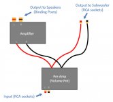
I want to connect the two, so I need to add a couple of stereo RCA outputs to my amplifier. However, I want them to be affected by the same volume pot that controls the levels of the main speakers, so I don't have to juggle the volume for the speakers and the subwoofer independently.
I've made a diagram showing what I think should work - any problem with the attached?
(Essentially, just splitting the output from the preamp - one set of wires to the amplifier and eventually the speaker outputs, and the other set of wires to RCA sockets which will feed the active subwoofer).
Thanks!
I am (extremely) new to this, so I apologise if this is a ridiculously simple question.
I'm busy building a DIY amplifier based on the HiFiMeDIY T1 amp.
I also have an active subwoofer with line-level stereo RCA inputs.
I want to connect the two, so I need to add a couple of stereo RCA outputs to my amplifier. However, I want them to be affected by the same volume pot that controls the levels of the main speakers, so I don't have to juggle the volume for the speakers and the subwoofer independently.
I've made a diagram showing what I think should work - any problem with the attached?
(Essentially, just splitting the output from the preamp - one set of wires to the amplifier and eventually the speaker outputs, and the other set of wires to RCA sockets which will feed the active subwoofer).
Thanks!
Attachments
Last edited:
Amplifiers are inverting or non-inverting? If either the power amp or subwoofer amp are inverting, there could be some caveats. If both amps are non-inverting and their input impedance is high enough, it should be no problemo.
The foolproof way to approach this is to provide a non-inverting, unity gain buffer to drive the subwoofer amplifier. A simple op amp will do. You could even incorporate a crossover into the circuit if you want to get fancy.
Using a buffer instead of a resistor divider avoids affecting the gain or frequency response of either amp. A resistor in series with the input of an amplifier (like you might have with a simple resistor divider) will affect the gain of a non-inverting amp and can affect the frequency response of a non-inverting amp with a low pass filter on the input. Many designs have a low pass filter right on the input (159 kHz is a typical corner frequency) and a series resistor will push that frequency down.
Using a buffer avoids all that drama.
Cliff notes: If you know both amplifiers are non-inverting and they both have reasonable input impedance (22K or higher would be ideal) then you can hook them up according to your diagram.
Also, if your subwoofer amp has a crossover circuit right at the input, with no buffer, then it would be wise to incorporate a buffer into your scheme.
Also, if your subwoofer amp has a crossover circuit right at the input, with no buffer, then it would be wise to incorporate a buffer into your scheme.
Check the output impedance of the volume control.
The higher that output impedance the less able this Source can drive other Receivers.
The reference to "buffer" is the same message.
Fit a buffer at the output of the volume control such that it can drive the two sets of cable and Receiver.
The higher that output impedance the less able this Source can drive other Receivers.
The reference to "buffer" is the same message.
Fit a buffer at the output of the volume control such that it can drive the two sets of cable and Receiver.
Check the output impedance of the volume control.
The higher that output impedance the less able this Source can drive other Receivers.
The reference to "buffer" is the same message.
Fit a buffer at the output of the volume control such that it can drive the two sets of cable and Receiver.
His preamp has a volume control right at the output? That's so many kinds of wrong.

A volume control should always be directly followed by a high bandwidth, low output impedance buffer, in order to mitigate effects on frequency and phase response. I know that there's a big trend towards passive "preamps" but there are some pitfalls. Common wisdom dictates low value potentiometers (10K is typical) and there's good reason for that. Typical commercial designs employ a high pass filter on the input. As I said, 159 kHz is a typical corner frequency (higher is better) and you don't want to push this number down.
I will share a real world design as an example. I'm prototyping a headphone amp with an input trap at 230 kHz. The filter consists of a 680 ohm resistor and a 0.001 uF ceramic capacitor. If the source drive impedance is 100 ohms, this turnover frequency is pushed down to 200 kHz. At 400 ohms, it is pushed down to 147 kHz.
If the corner frequency is 147 kHz, then the response of the amplifier will be down 0.1 dB at 14.7 kHz and there will be a small amount of phase shift too. Is the onset of intrusion high enough at 14.7 kHz? Is such a compromise acceptable? That is up to you and not me, but the point I'm making is that there is a trend here; a trend that can be mitigated by employing a simple buffer. It is trivial to build a high impedance buffer with an output impedance of 10 ohms of less. This allows you to use a higher value potentiometer if you wish and also allows you to drive long cables without as much concern with parasitic capacitance altering your design parameters.
It's always a big juggling game.
") Learn some good design habits, and stick with them.
Learn some good design habits, and stick with them.
Last edited:
The simplest non-audiophile way to do this is to use a voltage divider on the OUTPUT of the amplifier to create a signal for the input of the subwoofer. This is exactly what happens when your sub's plate amp has speaker level inputs. Inside there is a voltage divider network that has a relatively high impedance (e.g. 1k ohm) to ground and reduces the voltage by about 30dB (e.g. to about 3% of the incoming voltage). This can be connected to the line level inputs of the plate amp.
You can create the voltage divider by connecting the speaker level output to a 1k ohm 1/4W resistor, connect that to a 33 ohm 1/4W resistor, and connect that to ground. The junction between the two resistors is what you connect to the line level input of the sub amp. Make these connections at the sub amp and run a length of speaker wire in between.
You can create the voltage divider by connecting the speaker level output to a 1k ohm 1/4W resistor, connect that to a 33 ohm 1/4W resistor, and connect that to ground. The junction between the two resistors is what you connect to the line level input of the sub amp. Make these connections at the sub amp and run a length of speaker wire in between.
Last edited:
- Status
- This old topic is closed. If you want to reopen this topic, contact a moderator using the "Report Post" button.
- Home
- Amplifiers
- Chip Amps
- Adding RCA subwoofer outputs to diy amp