Hello,
I'm fairly new to the world of electronics, and I'm doing the best I can here, but I'm stuck, and cannot find a way out.
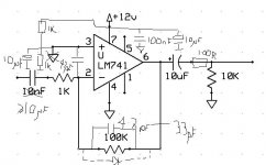
I have added a very basic preamp to my homebuilt guitar amp (based on the Hitachi HA13118 BTL Amp Chip) to boost input signal, but now that I have the right amount of signal, I have tons of RF noise, and no amount of shielding eliminates the problem. I sometimes even pick up radio stations.
Is there any way of eliminating all this RF in my circuit so that I can still keep the gain/output the way it is? Maybe use a different OPAMP?? I'm so confused! The sound is perfect otherwise... if I could only remove the buzz.
My basic preamp curcuit:
I have additionally tried to use a non-inverting setup with the LM741, and this just does not work. All I get is a pulsating. very upset speaker output, and no audio. I'm not really sure why this is happening, but it also happens when I try the same setup with a TL082.
Any help would be so very much appreciated.
thanks,
N
I'm fairly new to the world of electronics, and I'm doing the best I can here, but I'm stuck, and cannot find a way out.
I have added a very basic preamp to my homebuilt guitar amp (based on the Hitachi HA13118 BTL Amp Chip) to boost input signal, but now that I have the right amount of signal, I have tons of RF noise, and no amount of shielding eliminates the problem. I sometimes even pick up radio stations.
Is there any way of eliminating all this RF in my circuit so that I can still keep the gain/output the way it is? Maybe use a different OPAMP?? I'm so confused! The sound is perfect otherwise... if I could only remove the buzz.
My basic preamp curcuit:
An externally hosted image should be here but it was not working when we last tested it.
I have additionally tried to use a non-inverting setup with the LM741, and this just does not work. All I get is a pulsating. very upset speaker output, and no audio. I'm not really sure why this is happening, but it also happens when I try the same setup with a TL082.
Any help would be so very much appreciated.
thanks,
N
Are you using a positive and negative supply with that? it looks like the negative supply is just going to ground.
741 is very old OpAmp design, I think there are a lot better ones now.
I made a wah wah for my brother with one once about 20 years ago and it was pretty noisy, he liked it though")
741 is very old OpAmp design, I think there are a lot better ones now.
I made a wah wah for my brother with one once about 20 years ago and it was pretty noisy, he liked it though
I've tried that, but the second I do, I get a heavy pulsating in the speaker for about 3 seconds. Once the pulsating stops I tried the guitar, and I get a very reduced output.
The only way I get the output desired is through the circuit in my earlier post, albeit with the nasty noise.
The only way I get the output desired is through the circuit in my earlier post, albeit with the nasty noise.
The only way I get the output desired is through the circuit in my earlier post, albeit with the nasty noise.
But your circuit is nevertheless defective - it only amplifies one half of the waveform - which may be a cool thing for a guitar. Follow the suggestions above and make sure the PS lines are decoupled close to the opamp. If your biasing is correct you should get around half the supply voltage at opamp output. Does the buzz remain with the input shorted to gnd?
Is 10nF not too low at the input?
Besides adding the voltage divider, there are some other things you could change. The 10nF at the input should be increased to 10uF or so. If there is a long cable (anything above 30cm being considered long) connected to the output, a 220 ohm resistor between the op-amp and the cable may prevent the cable capacitance from making the op-amp unstable. If you pick up RF with the input wire, it may help if you split the 1kohm resistor into two 500 ohm (or 470 ohm) parts and add a 4.7nF capacitor from the point where the resistors are connected to each other to ground. Adding a decoupling capacitor directly between pin 7 and ground may also help, particularly if the wires to the supply are long.
Just because an IC is too slow to amplify RF doesn't mean it isn't affected by RF pickup. The contrary is often the case unfortunately !
So an input lowpass as Marcel mentioned is not a bad idea at all. I once used a cutoff frequency of 40 kHz on a bass guitar amp that proved to be O.K.
Another thing is the impedances involved. The typical impedances of guitar pickups are quite high. With your inverted circuit you have an input impedance of 1 kohms which is way too low unless your guitar has a built-in preamp.
You'd rather go for non inverting since this topology has higher input impedance. Even better, use a more modern opamp as well.
And yes: you have to watch out for the proper DC conditions as mentioned by the others above !
Regards
Charles
If your biasing is correct you should get around half the supply voltage at opamp output. Does the buzz remain with the input shorted to gnd?
When I connect Pin 3 to the voltage divider I do get half the supply voltage, but this is unusable since when I connect the output to the amplifier it causes a pulsation in the speaker as described earlier. I also noticed that with the circuit connected as in my initial diagram (pin 3 to GND), I get about 1.9V at output. Anything above ~2V will cause pulsation in the speaker. It appears that the amplifier cannot receive any more then this at input.
The 10nF at the input should be increased to 10uF or so.
I've tried this, and all it does is change the output frequency response. Less of the low end is filtered out, but the buzzing still remains.
If you pick up RF with the input wire, it may help if you split the 1kohm resistor into two 500 ohm (or 470 ohm) parts and add a 4.7nF capacitor from the point where the resistors are connected to each other to ground.
Adding the 4.7nF cap between the 2 seperate 470 ohm resistors does not help in reducing the buzzing. The leads are all very short (less then 2 inches).
You'd rather go for non inverting since this topology has higher input impedance. Even better, use a more modern opamp as well.
The non-inverting setup does not work either. I tried this early on, and as I said in my first post, all I get is the same pulsating as described above. Again, I think this is due to the fact that anything above ~2V at output of the preamp is not welcome by the amplifier.
I have recorded the buzzing in a .wav file that can be had here . Maybe I'm interpreting this sound incorrectly, but it sure sounds like RF to me.
thanks again,
N
I really hope that the value of "10n" for the input cap is a typo. With an input impedance of just 1k, you will need at least 100u (that's 10000 times higher) to prevent low frequency rolloff. Otherwise, you just create a high pass filter, and one with a gain of 40 dB at that. No wonder you have RF interference!
After you fix that, try a small ceramic capacitor between the + and - input pins to filter out RF noise. Try values between 0.001u and 0.1u. (Keep in mind that only ceramic caps have low enough parasitic inductance to be useful for filtering RF).
You need to listen to these folks when they tell you that you cannot connect the + input to ground, which is actually your negative supply, -Vee. It needs to be connected to a virtual ground which you can make with a voltage divider. Use no higher than 1 k resistors, due to your very low input impedance.
The 741 does not happily supply a gain of 100 (40 dB) by itself. It does not have the bandwidth (GBP) to do this well. Try two individual stages, each with a gain of 10 (20 dB). Or reconsider whether you really need such a high gain. I really don't think that you do, unless this is a microphone pre-amp.
The 10k resistor at the output will DC-reference the output to "ground" (which is actually your negative -Vee supply). Do you want this to happen? I would recommend removing it, but leaving the cap. I would also recommend a 100R resistor in series with the output. This will protect the opamp from capacitive loading caused by the cable that you use to connect it to the power amp, which can cause oscillations.
I also don't see any power supply decoupling in your schematic. Make sure to place a 0.1u cap between the +Vcc and -Vee supply pins of the opamp, physically close to the opamp.
Hi I have modified you circuit diagrams to show what I would have done and included some of the ideas from other people as well.
You will probably find that the 4.7pF to 33pF cap across the feedack resistor will solve the pulsing problems as your opamp is going badly unstable. This will also turn the circuit into an intergrator at high frequencies which will significantly reduce the effect of any RF noise picked up.
The PSU decoupling will also help with this 100nF will improve stability the 10uF improve the sound quality.
The cap accross the input pins should also reduce the RF suceptibility of the opamp and further reduce the problem.
You do need the two 1K resistors to bias the opamp to the middle of the operating voltage. I have included a smothing cap accross this, it may not be required if you are using a battery.
If you like the sound you are currenlty getting due to the half wave rectification of the signal. This is caused by you not using a voltage referance. You can recreate this correctly using a diode as shown in the diagram.
You should have some resistance at the output of the opamp to decouple the opamp from the cable capacitance this will improve the stability further and reduce the risk of damaging the opamp should you short the output to ground accidentaly. Ihave shown 100R.
Hope this helps
Andy
Attachments
N,
can you sketch out how this is connected to the power op amp, especially with respect to the power supply ? The output cap you have drawn **should** isolate it from DC but you have a resistor pulling it down to 0 volt (?). Does the power op amp run off +12 / 0 / -12 ? If it runs of +12 / 0 then you are pulling the input down to the supply rail - and it won't like this
Dave
Sounds like distortion to me, caused probably by the + input tied to the negative supply.I have recorded the buzzing in a .wav file that can be had here . Maybe I'm interpreting this sound incorrectly, but it sure sounds like RF to me.
DRC said:N,
can you sketch out how this is connected to the power op amp, especially with respect to the power supply ? The output cap you have drawn **should** isolate it from DC but you have a resistor pulling it down to 0 volt (?). Does the power op amp run off +12 / 0 / -12 ? If it runs of +12 / 0 then you are pulling the input down to the supply rail - and it won't like this
Dave
If your power amp is IGC and +12/0V PS, then copy the same circuit you already have above and ommit the 10uF cap at the output of 741 and the two res. after that. Your GC amp should have the 10uF amp at the input.
A 741 should not be use with a gain of 100 and it does not like running from a single supply.
You need an opamp like Analog Devices AD797, which can handle high gain, an is low noise and can run off a single supply. Also, you need to add some .01uf ceramic and 100uf tantalum caps added to the power supply to decouple power supply noise from the opamp. You might even need and 2mh coil in series with the supply.
You need an opamp like Analog Devices AD797, which can handle high gain, an is low noise and can run off a single supply. Also, you need to add some .01uf ceramic and 100uf tantalum caps added to the power supply to decouple power supply noise from the opamp. You might even need and 2mh coil in series with the supply.
Sorry for the delay in responding. I had to go out and buy some additional parts, and since Radio Shack is so well stocked, I had to take a major road trip.
Anyway, I have tried pretty much every suggestion listed, and let me say you guys are GREAT, but nothing seems to eliminate that noise. So, after deciding that I hate the LM741, I opted for using the TL082 Dual BiFET Opamp. I am only using 1/2 of the chip, but it seems to have eliminated the noise. In addition to swapping the chip, I also used some of gfiandy's suggestions (thanks so much btw).
Below is what I have ended up with. I'm still not sure that the TL082 is the right fit, but at least it doesn't produce that terrible buzz. If anyone had any suggestions for a better chip to use, I'll be glad to give it a shot. I will be trying the AD797 suggested by
jewilson (thanks).
I know there must be some additions/modifications to the current curcuit, but this is my starting point (see attachment). I'm particularly concerned with the input. If a very high impedence load is plugged in, I'm worried that it might blow the opamp.
Also, (stupid question I bet), but you guys all refer to a 100R resistor. I'm guessing this is 100 Ohms. Is this correct?
Thanks again,
N
Anyway, I have tried pretty much every suggestion listed, and let me say you guys are GREAT, but nothing seems to eliminate that noise. So, after deciding that I hate the LM741, I opted for using the TL082 Dual BiFET Opamp. I am only using 1/2 of the chip, but it seems to have eliminated the noise. In addition to swapping the chip, I also used some of gfiandy's suggestions (thanks so much btw).
Below is what I have ended up with. I'm still not sure that the TL082 is the right fit, but at least it doesn't produce that terrible buzz. If anyone had any suggestions for a better chip to use, I'll be glad to give it a shot. I will be trying the AD797 suggested by
jewilson (thanks).
An externally hosted image should be here but it was not working when we last tested it.
I know there must be some additions/modifications to the current curcuit, but this is my starting point (see attachment). I'm particularly concerned with the input. If a very high impedence load is plugged in, I'm worried that it might blow the opamp.
Also, (stupid question I bet), but you guys all refer to a 100R resistor. I'm guessing this is 100 Ohms. Is this correct?
Thanks again,
N
That looks a lot more reasonable.
You will probably notice less hiss if you replace the 56k resistors in your virtual ground with lower value ones. You can quite safely go as low as 1k. You have the right idea with the 100u cap to ground there too. Try to use a good low ESR type, like a Panasonic FC series or Nichicon Muse Fine Gold. Unless this pre-amp will be built into the same enclosure as the power amp, I would still highly recommend a 100 ohm resistor (1/4 W is fine) in series with the output, after the cap. This will help keep the opamp stable when connected to the interconnect cable.
The TL082 is adequate for audio, but it is an old design and is a bit noisy (hissy). You could also try the NE5532 or 5534 (also old but good), or any number of opamps from burr-brown (I've tried OPA2134 and OPA2604) or analog devices. The NJM4580 (aka JRC4580 or RC4580) is very popular in Japanese electronics and a lot of pro stuff (like Behringer). There is another active thread in this forum discussing opamps.
- Status
- This old topic is closed. If you want to reopen this topic, contact a moderator using the "Report Post" button.
- Home
- Amplifiers
- Chip Amps
- LM741 and RF NOISE!!!