With all the talk over counterfeit/fallout chips I got a giggle out of this. Saw the $.75 TDA2002 chip and thought I would take a look at it. Ad says "house numbered" and if you look at the numbers on the illustration/picture...
I'm sure it was just a mistake on the web site i.e. they wanted a 5 pin audio amp chip so he just grabbed what was available.
The TDA2002 is of practically no interest in this day and age. Only thing interesting about it is in one of the designs they use a pattern on the circuit board to make an inductor to block RF.
TDA2002
The data sheet was on jameco.com
I copied the relevant part of the pdf. Only mildly interesting in that everyone wants to reduce board area to a minimum so doing a RF inductor in copper clad pc board does not seem to be on anybody's hit list. I didn't bother to do any calculations of course. From experience with tuned circuits I would guess that size of inductor would be suitable for something in the 100-2000 MHz range. Depends on what cap you stick with it of course.
I copied the relevant part of the pdf. Only mildly interesting in that everyone wants to reduce board area to a minimum so doing a RF inductor in copper clad pc board does not seem to be on anybody's hit list. I didn't bother to do any calculations of course. From experience with tuned circuits I would guess that size of inductor would be suitable for something in the 100-2000 MHz range. Depends on what cap you stick with it of course.
Attachments
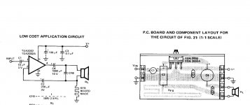
That is not a PCB inductor. It will have some inductance, but not much. Since it doubles-back on itself, the mutual inducatance of the parallel pairs of traces (with equal and opposing currents) will cause partial cancellation of the inductance. The inductance of this will be less than that of the equivalent length of straight wire. If it was a spiral shape, then it would definitely be an inductor. This is more reminiscent of a delay line used in high speed digital, such as memory circuits, where they are trying to match signal propagation times in a wide bus, making some traces longer by snaking them back and forth. Take a look at the traces leading to the memory chips on a PC video card or motherboard dimm sockets. In those cases, inductance is definitely not desired.
This appears to be a low value resistor. It is not clear what the purpose is, but it may be to set the DC gain. The AC gain seems to be set by capacitor ratios instead of resistor ratios. That's clever.
This appears to be a low value resistor. It is not clear what the purpose is, but it may be to set the DC gain. The AC gain seems to be set by capacitor ratios instead of resistor ratios. That's clever.
the tda2002 was used in cheap car radio applications.
schematic.......looks like current feedback. the speaker is the load (probably 4 ohms) and the spiral shape on pcb is a low ohm res (rfb) .
cfb (c feedback) is paralell to the speaker and limits the bandwith i think........
schematic.......looks like current feedback. the speaker is the load (probably 4 ohms) and the spiral shape on pcb is a low ohm res (rfb) .
cfb (c feedback) is paralell to the speaker and limits the bandwith i think........
"That is not a PCB inductor."
But then, you say it is an inductor, just a low value one so I think we all agree on that point. I've also made kits that operated in the 2 GHz range that used that same technique and called it an inductor.
"cfb (c feedback) is paralell to the speaker and limits the bandwith i think"
I think you are mostly right. I see that section of the circuit as operating in two ranges, otherwise: Why the inductor?
In the amplifier range we are interested in, cfb would be chosen to cut off bandwidth in a reasonable range. Adding an arguably extremely low value inductor, it would function just as if the inductor were ground. In the radio frequencies around 100 Mhz, it becomes a LC tuned circuit.
Since as you noted, it was a cheap car amplifier IC, IMO this was added to eliminate or reduce rfi from the ignition system.
You don't have to see what I am trying to say since it is academic at this point. I don't think anyone is going to build a TDA2002 based car stereo or hifi amp given the better solutions. I am a fan of killing two birds with one stone and economy of design. It looks to me like they just used circuit board traces to add an inductor and made the bandwidth capacitor function as both bandwith adjustment and RFI filter. Pretty clever if it actually worked! Of little practical value unless you live next to a radio station or maybe want to put an amp inside your computer.
Last edited:
Hi,
It is not an inductor and your just talking nonsense.
http://www.jameco.com/Jameco/Products/ProdDS/32897.pdf
It is a low value resistor that clearly sets the gain : Av-1 = RL/Rfb.
rgds, sreten.
It is not an inductor and your just talking nonsense.
http://www.jameco.com/Jameco/Products/ProdDS/32897.pdf
It is a low value resistor that clearly sets the gain : Av-1 = RL/Rfb.
rgds, sreten.
Last edited:
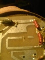
~2.3 GHz microwave reciever<VCO mixer/down converter> I built ~30 years ago and took a picture of about an hour ago. PC board inductor in addition to the others.
The cut on the PC board and glob of solder was just tuning to get it in the desired range. Very common technique for anyone that has even a basic knowledge of electronics.
Planar spiral coil inductor calculator
The cut on the PC board and glob of solder was just tuning to get it in the desired range. Very common technique for anyone that has even a basic knowledge of electronics.
Planar spiral coil inductor calculator
Attachments
Let's be clear, every conductor is an inductor, because current through any conductor produces a magnetic field and voila: inductance. That does not imply that every trace on a PCB is designed as an inductor, though some are. But it also means that you can't ignore the inductance of your PCB traces. In this case, the long snaking trace is designed as a resistor, but it will have some parasitic inductance. That inductance can likely be ignored at frequencies that this amplifier can operate within.
Right, I say it was probably done as it was to additionally block/bleed off high frequency ~RFI/EMI.
*IF* the designer just wanted to handle gain and/or feedback, HE WOULD HAVE JUST USED A $.06 RESISTOR!
The numbers don't add up. If you look at the values chosen in other designs, 100 nF to .47 uF cap, 1 Ohm to 10 Ohm resistor. 100 nF suggests something pretty far into the radio frequencies. The extra board area would cost more then the resistor it is supposed to replace if that was all he/she was doing.
I hope you realize that I agree it functions a normal resistor/cap filter, I have never said anything but that. Parroting back something that we all agree on accomplishes nothing except lets me know you are aren't reading what I wrote or don't have a grasp on what I said.
Remedial but if I say it is wet and sweet, and people repeat back 'it is sweet', well yeah, of course. The basic argument being used <and I am being generous saying it is an argument> is 'since it is sweet, it isn't wet' which just isn't valid.
I had a car amp that used these bridged. It was highly palatable at full blast. When I sold the car I kept the radio.  It is employed in the garage for those moments when I'm up to no good and need something pleasantly distracting. Practically, it will not combat the excessive noise from lack of proper lubrication, but the thing does succeed fairly well for most other purposes.
Fascinatingly, the treble resolution isn't awful when RF is prevented from hashing the tweeter. Conceivably a tweeter-side RC could do a similar job. At least it is more straightforward than customized speaker cables.
P.S. Singleton input amplifiers are probably best run from "tracking pre regulator" power. That uses gain to magnify the effectiveness of ordinary regulators (at the minor cost of an additional regulator in nesting config). That won't make anything louder, but sweeter may be suitable and it could do that.
It is employed in the garage for those moments when I'm up to no good and need something pleasantly distracting. Practically, it will not combat the excessive noise from lack of proper lubrication, but the thing does succeed fairly well for most other purposes. Fascinatingly, the treble resolution isn't awful when RF is prevented from hashing the tweeter. Conceivably a tweeter-side RC could do a similar job. At least it is more straightforward than customized speaker cables.
P.S. Singleton input amplifiers are probably best run from "tracking pre regulator" power. That uses gain to magnify the effectiveness of ordinary regulators (at the minor cost of an additional regulator in nesting config). That won't make anything louder, but sweeter may be suitable and it could do that.
This is a boring thread on a number of levels. Just for another laugh I used my DVM to measure a 4 inch trace. Resolution is .1 Ohm and it registered 0.0 Ohms. I found an 8" trace and finally got it to flip between .0 and .1 Ohm. Hard to tell if my DVM was properly zeroed so it could have been idling .049 Ohms.
I know what the designer stated purpose of the trace was. Just nothing here makes any sense. The resistance in the hook up wires would be higher. Same thing could have been accomplished by soldering the cap maybe 12" up the ground leg of the speaker wire and saying it was a resistor. As I said before, the design uses and extra $.30 worth of circuit board to eliminate a resistor that would probably cost less then $.6 in what was 'A low cost design.'
I spend a fair amount of time and money sorting things out. Did schematics for the Lepai, did some testing for the TDA2030 types and gave away the unused chips. Since there was some interest in single ended amps, I bought a Philips based one off of eBay to test it out even though I didn't particularly need it myself. Money and time don't mean much as long as I find it interesting. I just don't find anything interesting about the TDA2002 in 2014. If anyone wants to etch a circuit board and test it out, I will buy the parts for them. Just send me a private message with your address and I will have the parts shipped directly from the supplier. Much love guys.
I just have other things on my plate right now. Got gouged ~$20 for a LM4702 so that is on my hit list. Only a few passive components short of the build. I have to check out of here, it is making my head hurt looking at that circuit board.
Download this, most professional PCB designers have it on their desktops, its a good source for a lot of PCB based calculations:
Saturn PCB Design - PCB Via Current | PCB Trace Width | Differential Pair Calculator | PCB Impedance
A resistor costs more than just its selling price...A pcb trace resistor is free, requires no assembly, and the cost of PCB area is not that much for single sided designs.
These would have more self inductance than the initial traces, yet theses are not PCB inductors...
https://www.google.co.uk/search?q=l...5%2Feagle-matched-length-pairs-groups;770;602
Here is some pictures of planar inductor shapes:
https://www.google.co.uk/search?q=p...com%2Fdocument.asp%3Fdoc_id%3D1275810;350;295
- Status
- This old topic is closed. If you want to reopen this topic, contact a moderator using the "Report Post" button.
- Home
- Amplifiers
- Chip Amps
- For a laugh