About to build my first parallel chip amp, because I need lotsa watts into 4 ohms.
I'd like to use this thread to gather the issues that paralleling chip amps brings up. Some searching on diyaudio has revealed some that I will list here, but I'd be grateful for any other input.
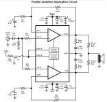
The schematic I will be using as a basis is the one in the LM4780 datasheet attached, though I will be using LM3886s.
1. Match feedback network resistors to 0.1%. No problem there.
2. Match NFB caps. This might prove difficult. I have a cap metre on my DMM, but it's not particularly accurate. I've heard a solution is to enormously oversize the NFB caps, up to 1000u. Presumably this low, no frequencies that are affected by any mismatch will be entering the amplifer due to input cap. I wondered if matching ESR might be necessary too, and wondered if it varied a lot from cap to cap.
3. Increase output resistors. 0.1 isn't reckoned enough, and 0.22 is preferred it seems, at the expense of damping factor, whatever that is.
Offset is an issue, I imagine, as if the two chips differ in offset you will have current flowing between them. At low volumes this may dominate. The high power app note (I forget its number) mentions using DC servo. I'd like to avoid this complication.
Any thoughts? Anything else I should be aware of?
I'd like to use this thread to gather the issues that paralleling chip amps brings up. Some searching on diyaudio has revealed some that I will list here, but I'd be grateful for any other input.
The schematic I will be using as a basis is the one in the LM4780 datasheet attached, though I will be using LM3886s.
1. Match feedback network resistors to 0.1%. No problem there.
2. Match NFB caps. This might prove difficult. I have a cap metre on my DMM, but it's not particularly accurate. I've heard a solution is to enormously oversize the NFB caps, up to 1000u. Presumably this low, no frequencies that are affected by any mismatch will be entering the amplifer due to input cap. I wondered if matching ESR might be necessary too, and wondered if it varied a lot from cap to cap.
3. Increase output resistors. 0.1 isn't reckoned enough, and 0.22 is preferred it seems, at the expense of damping factor, whatever that is.
Offset is an issue, I imagine, as if the two chips differ in offset you will have current flowing between them. At low volumes this may dominate. The high power app note (I forget its number) mentions using DC servo. I'd like to avoid this complication.
Any thoughts? Anything else I should be aware of?
Attachments
Last edited:
No one? I must have got everything right then.
Um... Dude. Some of us were asleep when you wrote...
")
About to build my first parallel chip amp, because I need lotsa watts into 4 ohms.
Use two chips rather than a dual chip-amp then. I also suggest reading National's app note, AN-1192 (commonly referred to as BPA200) on the thermal challenges involved.
I'd like to use this thread to gather the issues that paralleling chip amps brings up.
The issues are mostly related to thermal management. If you don't know how to calculate the thermal resistance of the needed heat sink, you will need to learn. The good news is that it's pretty simple. It's basically ohm's law with the following analogies:
Voltage (V, electrical) = Temperature (ºC, thermal)
Current (A, electrical) = Power (W, thermal)
Resistance (Ω, electrical) = Thermal resistance (ºC/W = ºK/W, thermal)
A 1 º increment in Kelvin (ºK) is equivalent to a 1 º increment in Celsius (ºC), hence, ºC/W and ºK/W are used interchangeably.
How to do the math is explained both in the LM3886 data sheet and in AN-1192.
The schematic I will be using as a basis is the one in the LM4780 datasheet attached, though I will be using LM3886s.
Good man!
1. Match feedback network resistors to 0.1%. No problem there.
0.1 % resistors are not that expensive anymore. 0.05 % or 0.02 % are available for a (relatively small) premium.
2. Match NFB caps.
Or use a DC servo. I'd prefer the servo as it's much easier to get good matching between channels that way.
3. Increase output resistors. 0.1 isn't reckoned enough, and 0.22 is preferred it seems, at the expense of damping factor, whatever that is.
You'll burn an ungodly amount of power in the output resistor. I suggest trying with 0.1 Ω first and only increasing to 0.15 or 0.22 Ω if necessary. You'll probably need a 7 W or 10 W type if you go with a 0.22 Ω. Do the math...
Offset is an issue, I imagine, as if the two chips differ in offset you will have current flowing between them.
True. So the amp burns a bit more power at idle. Big whoop... None of that current flows through the speaker, so I fail to see how this is an issue for sound quality.
~Tom
Well, I did, and with the typical 68 W into 8 ohms that the '3886 is good for I'm getting 1.8 W of dissipation.You'll burn an ungodly amount of power in the output resistor. I suggest trying with 0.1 Ω first and only increasing to 0.15 or 0.22 Ω if necessary. You'll probably need a 7 W or 10 W type if you go with a 0.22 Ω. Do the math...
Everyone and their dog is using .22 ohm 5 W emitter resistors in regular 100-150 W amps. Guess why?
.22 ohms of output R are good for a nominal damping factor of 36 with an 8 ohm load. (Ditto for .11 ohms and 4 ohms.) Not great but workable - 0.11 ohms is the equivalent of a good 6 meters of AWG14 twin lead, or 8 m of 2.5 mm². If you know the minimum and maximum speaker impedance in the audible range, you can calculate the resulting frequency response deviation.
Last edited:
Well, I did, and with the typical 68 W into 8 ohms that the '3886 is good for I'm getting 1.8 W of dissipation.
±28 V swing into 4 Ω would be 4.7 A RMS (accounting for 1.6 V drop-opt across the LM3886). 4.7 A in 0.22 Ω dissipates 4.8 W.
A 5 W rated resistor at 25 ºC ambient would reach nearly 250 ºC under those conditions. That's why I normally derate the resistors by 3~4x. So you'll need a 15~20 W rated resist.
With 0.1 Ω, the dissipation is 2.2 W. Now a 5 W type would actually have a chance of surviving a full-power sine wave test. A 7 W would be better...
You can, of course, argue that due to the crest factor of music, the power dissipation is less for typical program material at max output power. In the old days, crest factors on the order of 10~20 dB were common. These days with the hyper-compressed music, don't expect much above 3~6 dB.
Everyone and their dog is using .22 ohm 5 W emitter resistors in regular 100-150 W amps. Guess why?
The emitter resistors only see half the current as each side of the output stage conducts during alternate cycles of the sine wave. In a 100~150 W amp, you also generally have multiple output devices in parallel, each with their own 0.22 Ω resistor. This reduces the power dissipation per resistor even more.
~Tom
Last edited:
- Status
- This old topic is closed. If you want to reopen this topic, contact a moderator using the "Report Post" button.
- Home
- Amplifiers
- Chip Amps
- The Perils of Paralleling