You're telling me that I'm supposed to pay $40 to see the article? Anyway, I think I've already read that article, and IIRC all that in needed is to place a small compensation capacitor in parallel to shunt resistor in T-feedback network, and IIRC it's there only to extend a freq. response a tiny bit comparable to non-inverted wired opamp.
I am telling you where the link is and that the T network would have a negative effect on the amplifier bandwidth and that it needs compensation. Use it yourself if you want to.
Your thoughts are always welcome 🙂, if you mean the compensation cap parallel to the feedback resistor (the series RC branch) i can add that. As for the output R//L network i'll leave it out for now and add it later if the speaker cable combination need it.
That's the plan. 🙂
If you mean the power on thumb, the power supply have a soft start circuit with a rather large start up time so i guess that will help?
Best regards.
I'm not so sure just how silent the switch on will be even with a slow start. Its an unanswerable question unless someone has actually done it. That said, many commercial amps are far from silent at power on and off... I guess it depends what is and is not acceptable to you. Adding a speaker delay afterwards is dead easy though (if it needs it).
Reversed speaker sockets are fine. No one but you would know 😀
Stability... your going to have to prove the design by building it. No matter how comprehensive the simulations and thought that goes into it all, at the end of the day you have to dangle something awkward on the end of it all and confirm its well behaved.
 As a public forum all members have a right to post here as long as their response meets forum guidelines. No one has a right to request another forum member not to post. If you do not like the message that is what your ignore list is for.
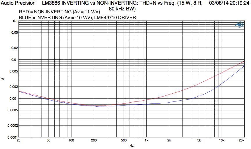
Looks very similar to what I used for my inverting vs non-inverting test.
I suggest using an actual zener regulator rather than just the zener diode. Recall, you have a 1 kOhm input impedance on the LM3886, so the worst case output current of the LME49710 is about 15 mA. Add to that the worst case LME supply current and whatever current is needed to keep the zener happy and you'll burn almost 1 W in the series resistor (R2, R3). Instead, I suggest using an emitter follower:
Build the negative regulator using a PNP. I'd add a cap across zener as well.
You could also use the LM317/LM337. They come in a 100 mA version in a TO-92 package.
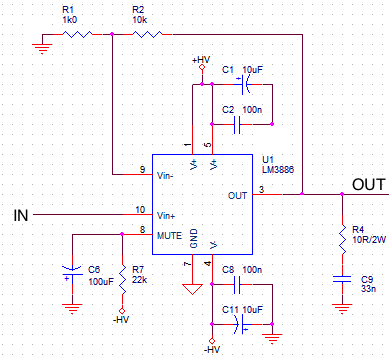
I don't think C1 is a good idea. You want the load current of the LM3886 to flow from the VCC bypass cap through the load and back to the ground end of the VCC bypass cap. Similarly for the negative swing, just the VEE bypass cap instead. Coupling the two supplies will probably degrade the PSRR. Best case, it has no effect at all.
C8 on the input is mentioned in the datasheet as a way to tame "quasi-oscillations" near clipping. Unless this is an issue for you, I'd leave it out as it really impacts stability. See my post in "Improving the LM3886", Post #66.
I suspect you may find that 47 nF, 4.7 ohm or 33 nF, 10 ohm work better for the Zobel, but you can experiment with that. Just remember to size the resistor to handle the dissipated power of a rail-to-rail swing at 20 kHz.
~Tom
I suggest using an actual zener regulator rather than just the zener diode. Recall, you have a 1 kOhm input impedance on the LM3886, so the worst case output current of the LME49710 is about 15 mA. Add to that the worst case LME supply current and whatever current is needed to keep the zener happy and you'll burn almost 1 W in the series resistor (R2, R3). Instead, I suggest using an emitter follower:
An externally hosted image should be here but it was not working when we last tested it.
Build the negative regulator using a PNP. I'd add a cap across zener as well.
You could also use the LM317/LM337. They come in a 100 mA version in a TO-92 package.
I don't think C1 is a good idea. You want the load current of the LM3886 to flow from the VCC bypass cap through the load and back to the ground end of the VCC bypass cap. Similarly for the negative swing, just the VEE bypass cap instead. Coupling the two supplies will probably degrade the PSRR. Best case, it has no effect at all.
C8 on the input is mentioned in the datasheet as a way to tame "quasi-oscillations" near clipping. Unless this is an issue for you, I'd leave it out as it really impacts stability. See my post in "Improving the LM3886", Post #66.
I suspect you may find that 47 nF, 4.7 ohm or 33 nF, 10 ohm work better for the Zobel, but you can experiment with that. Just remember to size the resistor to handle the dissipated power of a rail-to-rail swing at 20 kHz.
~Tom
The new schematic, it is based on Bob Cordell's super clone, any input is welcome...
An externally hosted image should be here but it was not working when we last tested it.
Best regards.
One thing to keep in mind: If you want performance similar to what I measured, you have to pay attention to the layout of the LME49710 part of the circuit. I took the ground for the LME at the star ground point in the LM3886 circuit.
~Tom
~Tom
Looks very similar to what I used for my inverting vs non-inverting test.
I suggest using an actual zener regulator rather than just the zener diode. Recall, you have a 1 kOhm input impedance on the LM3886, so the worst case output current of the LME49710 is about 15 mA. Add to that the worst case LME supply current and whatever current is needed to keep the zener happy and you'll burn almost 1 W in the series resistor (R2, R3). Instead, I suggest using an emitter follower.
Build the negative regulator using a PNP. I'd add a cap across zener as well.
You could also use the LM317/LM337. They come in a 100 mA version in a TO-92 package.
Hi there Tom, 🙂
Are there any other drawbacks to just using the simple zener other than wasted energy? I'll use the regulators (100mA version) if i can source them also can i use 7815/7915 (also the 100mA version)?
I don't think C1 is a good idea. You want the load current of the LM3886 to flow from the VCC bypass cap through the load and back to the ground end of the VCC bypass cap. Similarly for the negative swing, just the VEE bypass cap instead. Coupling the two supplies will probably degrade the PSRR. Best case, it has no effect at all.
C8 on the input is mentioned in the datasheet as a way to tame "quasi-oscillations" near clipping. Unless this is an issue for you, I'd leave it out as it really impacts stability. See my post in "Improving the LM3886", Post #66.
~Tom
I see your point and will remove C1 and C8. Interesting read in posts #66 and #67.
Can i try 22nF+15 Ohm (2W)?I suspect you may find that 47 nF, 4.7 ohm or 33 nF, 10 ohm work better for the Zobel, but you can experiment with that. Just remember to size the resistor to handle the dissipated power of a rail-to-rail swing at 20 kHz.
~Tom
One big question though, in your PCB i couldn't find the output R//L network it's there in the layout but not on the actual board was that for test purposes only?
Thanks Tom for your time and for your valuable input.
Best regards.
Last edited:
One thing to keep in mind: If you want performance similar to what I measured, you have to pay attention to the layout of the LME49710 part of the circuit. I took the ground for the LME at the star ground point in the LM3886 circuit.
~Tom
In a couple of days i'll post the layout and be assured i'll keep all previous advice in mind.
Ground of the buffer goes to the signal star ground connected to the power ground through 4.7 Ohm. I've tried this before and i guess it'll work here as well
Best regards.
Last edited:
Are there any other drawbacks to just using the simple zener other than wasted energy?
Other than wasted power, size, reliability, and cost, no I can't think of other drawbacks... 😉
I'll use the regulators (100mA version) if i can source them also can i use 7815/7915 (also the 100mA version)?
The 1.5 A LM317/337 or LM7815/7915 will work just as well as the 100 mA versions. They'll just be bigger and (probably) more expensive. I think the LM317/337 are lower noise than the 7815/7915, hence my suggestion.
Can i try 22nF+15 Ohm (2W)?
I was reading Douglas Self's book the other night to figure out the Zobel network. He mentions that 100 nF, 10 ohm seems to be the sweet spot. The Parasound A23 I took apart a while back due to water damage, had 10 ohm, 33 nF as I recall. I'd try to keep R*C roughly the same as National used in the data sheet (2.7 ohm, 100 nF). Something like 27 nF, 10 ohm should work. 22 nF, 15 ohm was what I used in my P2P setup. I'd have to do a full stability analysis to give a better answer (still waiting for gear to arrive so I can measure GM, PM).
One big question though, in your PCB i couldn't find the output R//L network it's there in the layout but not on the actual board was that for test purposes only?
I did not use the R||L network in my test set-up. There are footprints for the components on the board, though. That's L1 and R3. Note that this layout is very, very un-optimized. As you noticed in the LM3886 PCB vs P2P (with data) thread, I learned a lot building this circuit and need to transfer that knowledge to the PCB. At the very least, the Zobel network (C9, R4) need to move **A LOT** closer to the IC.

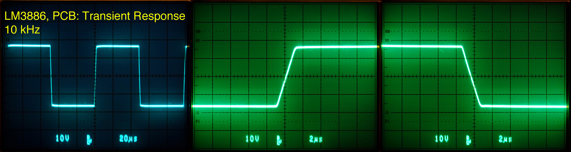
That said, it measures pretty well and shows no signs of instability (judging by the transient response anyway).
~Tom
Last edited:
I was reading Douglas Self's book the other night to figure out the Zobel network. He mentions that 100 nF, 10 ohm seems to be the sweet spot. The Parasound A23 I took apart a while back due to water damage, had 10 ohm, 33 nF as I recall. I'd try to keep R*C roughly the same as National used in the data sheet (2.7 ohm, 100 nF). Something like 27 nF, 10 ohm should work. 22 nF, 15 ohm was what I used in my P2P setup. I'd have to do a full stability analysis to give a better answer (still waiting for gear to arrive so I can measure GM, PM).
I'll be waiting for these results right now i guess i am going with the 22nF+15 Ohm combination.
I did not use the R||L network in my test set-up. There are footprints for the components on the board, though. That's L1 and R3. Note that this layout is very, very un-optimized. As you noticed in the LM3886 PCB vs P2P (with data) thread, I learned a lot building this circuit and need to transfer that knowledge to the PCB. At the very least, the Zobel network (C9, R4) need to move **A LOT** closer to the IC.
That said, it measures pretty well and shows no signs of instability (judging by the transient response anyway).
~Tom
Please don't optimize it, if it measure the way you showed, that gives the optimum performance according to the datasheet figures. 🙂
Best regards.
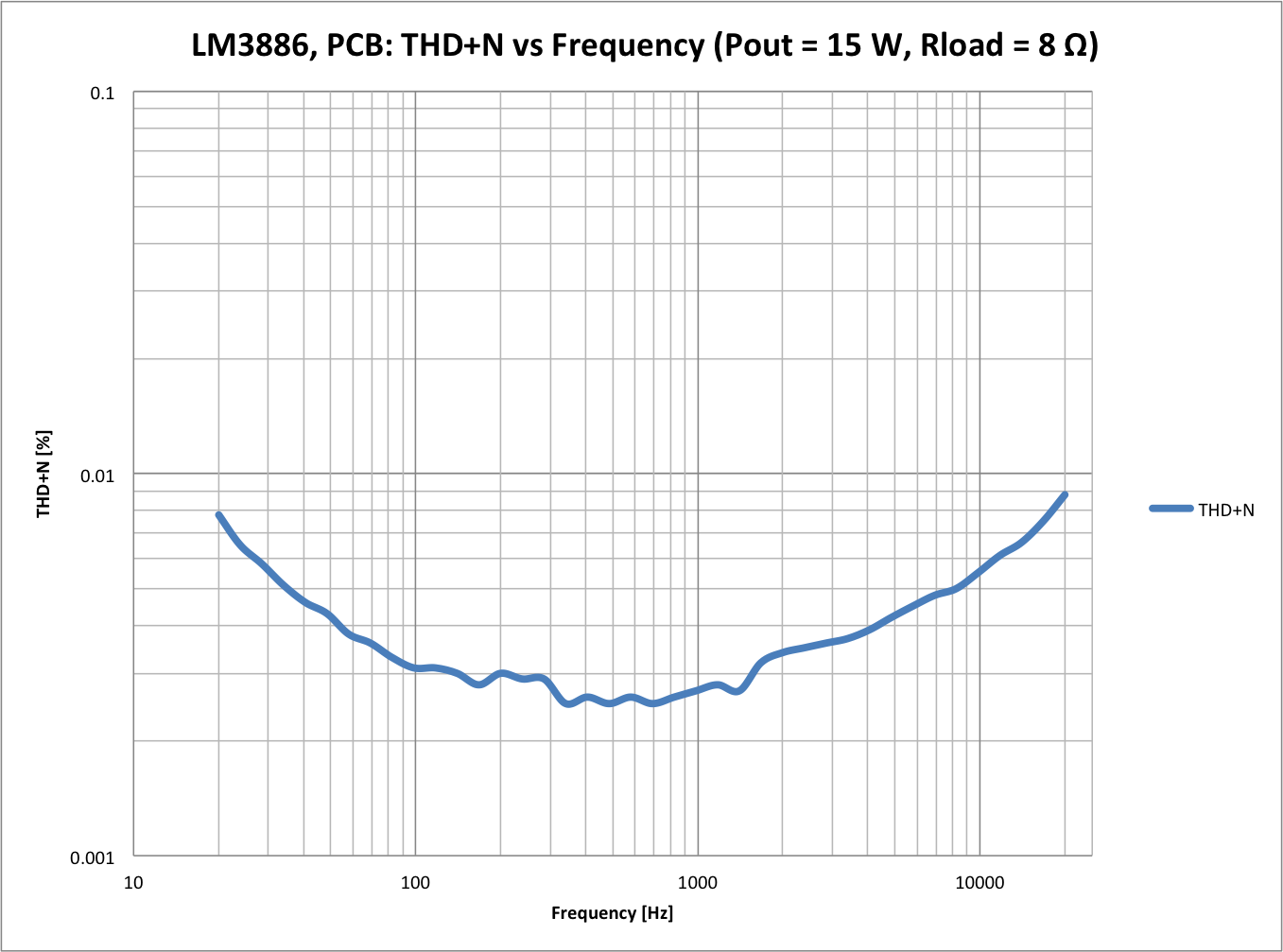
If, by optimizing the PCB, I can achieve the performance of my P2P circuit (see below), I'd say the optimization is definitely worth it. Regardless, the Zobel network does need to move closer to the LM3886 and its parasitic inductance (trace length) minimized. I'm sure my stability measurements will confirm this.
~Tom
~Tom
That said, it measures pretty well and shows no signs of instability (judging by the transient response anyway).
Tom, what is the load?
Edit: With input filter in situ?
Last edited:
Tom, what is the load?
Edit: With input filter in situ?
8 ohm. Minimal cap (probably a few hundred pF). Need to revisit transient vs capacitive load.
No input filter. Exactly as shown in the schematic except the bypass caps were 47 nF not 100 nF. I also had 1000 uF where the power entered the circuit. The circuit was powered by a pair of lab supplies. I was aiming to optimize the LM3886 part of the circuit, hence the lab supplies.
~Tom
Without compensating capacitor across Rf? If that's the case could you show as a response at 1kHz?
Yes. Without the Cf+Rf2 across Rf1 (designators referring to those in the data sheet AC Test Circuit #2).
Which response at 1 kHz are you looking for? Transient response? It'll be the same as that at 10 kHz. The transient response measures the amp's response to a step function. The reason the transient response is measured at 10 kHz is that if there's any overshoot or ringing on the response, it's usually in the low MHz range, hence, not visible on a long time scale. With the 200 us/div time scale needed to show a full period at 1 kHz, that ringing would be a little blip that's barely noticeable on the o'scope. To see the ringing, you need a shorter time scale. By 20 us/div (enough to show a full period at 10 kHz) you can usually pick out the ringing if there is any. Hitting the 10x magnifier shows the detail.
Note that my measurement was done with resistive load. Minimal cap loading (basically Cload = capacitance of test leads and equipment). I will measure versus cap load, but I need some test equipment to arrive first.
If I misunderstood your question and you were after a different response, please specify which response you'd like to see. There are many responses... Frequency (subdivided into amplitude and phase responses), step response (shown), impulse response, etc.
~Tom
Last edited:
Hi all,
Here are the first attempt at the board layout (one channel) along with the last updated schematic, your input would be most welcome.🙂


Best regards.
Here are the first attempt at the board layout (one channel) along with the last updated schematic, your input would be most welcome.🙂
Best regards.
Which response at 1 kHz are you looking for? Transient response? It'll be the same as that at 10 kHz. The transient response measures the amp's response to a step function. The reason the transient response is measured at 10 kHz is that if there's any overshoot or ringing on the response, it's usually in the low MHz range, hence, not visible on a long time scale. With the 200 us/div time scale needed to show a full period at 1 kHz, that ringing would be a little blip that's barely noticeable on the o'scope. To see the ringing, you need a shorter time scale. By 20 us/div (enough to show a full period at 10 kHz) you can usually pick out the ringing if there is any. Hitting the 10x magnifier shows the detail.
Yes, I was looking for 1k transient response, "hoping" I'll see a little overshot and ringing. Your response was more than I had hoped for, thank you.
- Status
- Not open for further replies.
- Home
- Amplifiers
- Chip Amps
- Inverting LM3886