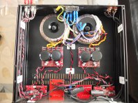
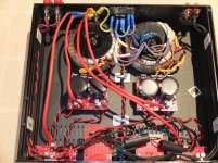
Hi, here's a pic of internals on my amp, as you can see I've only earthed the IEC socket at the moment, but having read almost every post on grounding, for safety issues, I know that I need to ground PSU and amp board at least.
I consulted an electronics engineer who said that my voltages are 'floating' which may explain how I've got 80mv, and 120mv dc offset at outputs (see my earlier thread that died from no further input)
It has been said here somewhere, that dual mono's suffer more from earth loops so I'm worried about that when I come to grounding (star?), or should I just do it and see if I get a hum?
Also, what to ground?
The speaker and RCA's are both isolated from the case, as are the PSU boards, as they're on nylon standoffs.
If I do have to build 1 or 2? Isolation circuits, I know about the 35A bridge rectifier, but at what voltage?
I read (I think) from the very knowledgeable AndrewT, that it need be no more than 50v, but at Farnell the 100v units are cheaper than the 50v ones, so will this do?
I'm buying from Farnell as they're the only people that do the Mentor dials that I want and have to build up to minimum £20 order.
Many thanks to all, especially AndrewT, and by the way, I HAVE read hundreds of posts to try to get here.
Attachments
Here's what I unearthed, and I know it's not quite the same, using two cases, but I'm thinking the principal's the same.
BTW info on BrianGT Dual Mono kit:
Toroidals are:120va 25v secs, those are Ansar Supersound 2.2f caps on amp inlets to act as DC blockers, the optional cap for lowering DC offset was not used on amp board following elec engineer's advice, selector switch and Alps pot also from BrianGT
BTW info on BrianGT Dual Mono kit:
Toroidals are:120va 25v secs, those are Ansar Supersound 2.2f caps on amp inlets to act as DC blockers, the optional cap for lowering DC offset was not used on amp board following elec engineer's advice, selector switch and Alps pot also from BrianGT
Attachments
Using a bridge rectifier as part of a ground-loop breaker (you must have the RC circuit in parallel with the bridge) is not necessarily legal, but if you do it, the voltage of the bridge doesn't matter because it will never be reverse-biased. It's either off (less than 1.4V between power and safety grounds, only the RC are conducting), or it's conducting and clamping to about 1.4V.
That second diagram you post is the wiring diagram for the supply rectifiers, which has nothing to do with grounding. The first diagram showing a bridge at the bottom left; that's a third (fifth?) and completely separate bridge.
The point of the bridge in the ground-break circuit is to clamp fault currents to ground so that if a wire escapes and touches the chassis, the current all goes to earth and a fuse or RCD/ELD trips. Without the bridge there, a dangerous voltage would develop across the RC. The bridge must therefore have a very high current rating: no less than 35A, preferably 50A or 100A. The most important thing is that it must absolutely have a significantly larger I2T rating than your house breaker or you are introducing an electrocution hazard.
Without the RC, the ground breaker won't conduct at small (<1.4V) voltages and won't conduct RF.
Last edited:
Thanks laplace, with regard to what I should ground, the reason I'm puzzled is that the amp works the way I've wired it, and I don't understand what the zero volt line is shown on that second diagram (this is one of the ones that I read I should ground).
BTW, the toroidal trafos, which actually are 160va, say ClassII (class B) does this mean they're double insulated? Does this also affect grounding?
Many thanks
BTW, the toroidal trafos, which actually are 160va, say ClassII (class B) does this mean they're double insulated? Does this also affect grounding?
Many thanks
Thanks laplace, with regard to what I should ground, the reason I'm puzzled is that the amp works the way I've wired it, and I don't understand what the zero volt line is shown on that second diagram (this is one of the ones that I read I should ground).
BTW, the toroidal trafos, which actually are 160va, say ClassII (class B) does this mean they're double insulated? Does this also affect grounding?
Many thanks
The transformers are double-insulated and must be so because you don't have physical access in order to ground their cores. If you used a non-toroidal (E-core) transformer, you would need to ground the core for safety, usually by bolting it to the grounded chassis.
Yes your amp will work fine while it works but if it fails it can be a hazard because the audio ground is not attached to safety ground. Consider the following scenario:
- loud music, transformer overheats
- insulation melts between primary and secondary coils
- primary/secondary short to each other at a single point
- you have mains voltage on one of the speaker leads
- the amplifier is still operating and sounds fine
Which is quite hazardous, I'm sure you will agree.
The simplest and almost-certainly sufficient solution is to tie your power ground to safety ground. Run a separate wire from each of the 0V lines (transformer center-taps) back to the frame ground point. It will then be much safer and will probably have no audible issues from grounding. If it sounds good at that point, leave it alone.
You only need a ground-break circuit if attaching the ground point causes hum from a ground loop, eg between your amplifier, a source, their interconnects and their separate mains cables. If such a thing occurs, the better option is not to interfere with the safety ground but to have a non-zero impedance (10R?) in series with the input ground line, ie isolate the RCA outer conductor from (frame) ground and put a resistor between the RCA outer and the input ground on the amp board.
Edit: the 0V (fat black) line on that first diagram is all four of your black wires coming out of the bridge+filter PCBs.
PS: you should use different colors for +V and -V, and (assuming that central pair is switched mains), only brown+blue for mains.
Last edited:
Hi thanks once again for your input.
Here's a pic once I grounded the power lines (0V on PSU boards and CHG on amp boards) why anyone would want to ground any of the speaker posts or RCA posts is beyond me, for safety's sake this is all I can see needs grounding as you said.
Well I fired it up and no hum at all.
I was actually quite disappointed that there wasn't any, as I'd worked myself up into thinking I'd definitely get some.
Maybe because I kept all the signal wires away from the power lines.
Now all I need to do is to post the picture on the sticky of what it looks like outside, as the observant amongst you noticed I've got the chips on the front of the amplifier, and that was NOT by accident.
It may take a week or so as I'm waiting for knobs to complete the controls.
BTW, the switch on the front is single pole, and anyway, I'm the only one's going to use this amp so I'm not bothered about colours, as you can see from grounding wires.
Attachments
Hah, you've got even more grounds there than you need now. You don't need to ground both ends of the PSU->amp cables! Just one will do. The only drawback is possible hum and if you have none, then just leave it be.
Indeed, your signal and power cables are very nicely separated and that has a lot to do with why your amp is quiet.
Indeed, your signal and power cables are very nicely separated and that has a lot to do with why your amp is quiet.
When you say 120mV and 80mV offsets, I presume that's the voltage across the outputs, not from the outputs to ground? Grounding the amplifier properly won't change that, it will just make sure that the negative speaker terminal is at ground.
Those offsets seem high to me (my LM3886s are at about 2-5mV each). Did you use an input capacitor? If not, you should.
Those offsets seem high to me (my LM3886s are at about 2-5mV each). Did you use an input capacitor? If not, you should.
Hi, I measured them at speaker posts (across the outputs, as the speaker grounds are connected to the boards) both with no load and also with the speakers working, I figured that anything measured there would go on to speakers themselves.
I didn't use Ci on advice of an electronics engineer (he thinks that the amps are generating the voltage) but I used an Ansar supersound 2.2f polypropylene caps on each input as a dc blocker, incidentally, either side of these caps there's no DC voltage to speak of either.
It's almost as if this is generated entirely on each amp board.
I haven't checked the datasheet but I assume that Ci is the feedback cap? If you don't have the feedback cap, then any inherhent dc offset in the chips themselves will be multiplied by the gain of the amp and show on the output. Input cap will not change this. The feedback cap ensures that the gain is 1 X at DC.
edit: also I believe that dc offset should be measured with input shorted, and prefferably with a dummy load on the output.
Tony.
edit: also I believe that dc offset should be measured with input shorted, and prefferably with a dummy load on the output.
Tony.
Last edited:
Thanks Tony, yes you're correct that Ci is feedback cap and I didn't fit it on account that it seems to be widely regarded as detrimental to sound quality.
I do also remember reading somewhere about shorting the input terminals, and also about a dummy load on the output, would I be right in assuming a 10ohm resistor? or have I concocted that figure in my head?
I'll do the test with the inputs shorted in case it would make a noticeable difference, and report back here.
I'm aiming for an offset below 100mv (as per BrianGT's website instructions), one's already there, but I still need to drop the other channel.
Incidentally, if I don't manage it, in real terms what difference would be noticed at 120mv? Would I damage my speakers, would the sound be inferior? Etc etc.
Yeah, you need the feedback capacitor otherwise the output offset will be the loop gain (probably around 18 to 23 depending on the kit you used) multiplied by the input offset, which is a few mV and varies chip-to-chip. If you want no output offset without the feedback cap, you need to either build a DC servo for the input - which amounts to putting a cap in the feedback just more complicated - or you need to put in a trimpot arrangement to give it some input offset to null the amplifier's own offset.
Just put the capacitor back. If it's properly chosen, it won't affect your low-frequency response since I refuse to believe you're driving a subwoofer capable of 10Hz with an LM3886")
And if you don't believe me, put it back into one channel in order to make an experiment. Can you hear the difference between channels? No? Then it's not detrimental to sound quality.
In terms of effect on sound, it depends on your speakers. If you're running passive crossovers (the usual arrangement), the DC offset will cause a small cone offset on your woofer that is likely entirely irrelevant; the offset is probably smaller than manufacturing tolerances on cone centering so you stand as much chance of improving the sound as worsening it. If you're using the 3886 to directly drive tweeters in an active-crossover system then an offset might cause increased even-order distortion by running the voice coil in one side of the gap, i.e. the speaker will have more sensitivity travelling one way than the other. It's a big maybe, depending on the speaker design, gap width, coil length, etc, etc. Better not to have the offset though.
Just put the capacitor back. If it's properly chosen, it won't affect your low-frequency response since I refuse to believe you're driving a subwoofer capable of 10Hz with an LM3886
And if you don't believe me, put it back into one channel in order to make an experiment. Can you hear the difference between channels? No? Then it's not detrimental to sound quality.
In terms of effect on sound, it depends on your speakers. If you're running passive crossovers (the usual arrangement), the DC offset will cause a small cone offset on your woofer that is likely entirely irrelevant; the offset is probably smaller than manufacturing tolerances on cone centering so you stand as much chance of improving the sound as worsening it. If you're using the 3886 to directly drive tweeters in an active-crossover system then an offset might cause increased even-order distortion by running the voice coil in one side of the gap, i.e. the speaker will have more sensitivity travelling one way than the other. It's a big maybe, depending on the speaker design, gap width, coil length, etc, etc. Better not to have the offset though.
- Status
- This old topic is closed. If you want to reopen this topic, contact a moderator using the "Report Post" button.
- Home
- Amplifiers
- Chip Amps
- What needs grounding on LM3886, and what voltage bridge rectifier for ground loop