Would you shed some light on these common pitfalls?
Whilst I'm not AndrewT I have posted in the past about some of the pitfalls of these posted designs. One has already arisen on this thread - the need to have closely matched capacitors in the gain setting networks. Another is the mentioning of 1% resistors which simply aren't close tolerance enough. A third is the use of too low (0.1R) sharing resistors. A fourth is suggesting that the sharing resistors need to be fairly close tolerance, leading to punters wasting money.
One could forego the capacitors and use a DC servo... That would make it possible to use 1 % tolerance caps rather than the typical electrolytic type with +/-10 ~ +/-20 % tolerances.
The BPA200 app note (AN-1192) actually has a lot of information on component selection. The LM3886 datasheet offers a bunch of information on supply bypassing. I suspect most trouble is caused by inadequate supply bypassing.
I do agree that 0.1 ohm is a bit low for the sharing resistors. 0.22 or 0.33 ohm would seem more reasonable.
~Tom
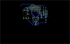
Thank so much for your interest to help, today i start to design a new pcb because the old one was copy paste from diyaudio, thing that never happened again usualy i made my owns but i was lazy and i got a few full days busy because that , the troubles comes from pcb...so today i start to design a pcb so what do you think about it
Thanks
Thanks
Attachments
I suggest adding some 100 nF X5R/X7R ceramic dielectric bypass caps. I would have something like 1000 uF where the power enters the board and 10 uF || 100 nF near the chip.
If you want to get fancy, you could look up the ESR and ESL (parasitic resistance and inductance) of the caps you're using and set up a simulation in Spice. You need to select the capacitors such that the impedance of the capacitors remain low up into at least the low MHz range (higher is better).
Make the supply traces as wide as you can fit on the board.
~Tom
One thing to think about: With two amplifiers in one package, you dissipate all the power in one package. This creates a bit of a thermal challenge. If you are aiming for higher output power, I suggest switching to two LM3886 instead. The total power dissipated is the same, but it's spread out across two packages, hence, easier to manage.
If you're building the circuit to try it out and/or for sound quality reasons and don't intend to operate at max power for any length of time the dual amplifier IC will probably work fine.
Just sayin'... The thermal issues are described pretty well in the BPA200 app note (Analog, Embedded Processing, Semiconductor Company, Texas Instruments - TI.com - search for BPA200).
~Tom
- Status
- This old topic is closed. If you want to reopen this topic, contact a moderator using the "Report Post" button.
- Home
- Amplifiers
- Chip Amps
- LM4780 parallel bad distorsion