In my endeavour to build a subwoofer circuit myself I ame across this awesome schematics by NHT, however while I was trying to plot it in circuit maker 2000 to print pCB I came across this mystery component whose symbol is attached can anyone help identifying it and suggets alternate components.
Attachments
IF you're sure the component is a light dependent resistor it can bee somthing like : VTL5C3, VTL5C3/2
If its a opto kopled transistor it can bee somthing like the well known CNY17. Found bouth at http://www.elfa.se/en/
If its a opto kopled transistor it can bee somthing like the well known CNY17. Found bouth at http://www.elfa.se/en/
RE:
Well the BMP is exactly what is mentioned in the schematic and is located at htt://www.nhthifi.com under support, and then schematics by the name of NHT sub 2i controller on page 4 of the PDF file in the section of overshoot controller, appreciate if you could have a look at it, however there is no harm in using a combo of LDR-LED but need further help in this respect,
Well the BMP is exactly what is mentioned in the schematic and is located at htt://www.nhthifi.com under support, and then schematics by the name of NHT sub 2i controller on page 4 of the PDF file in the section of overshoot controller, appreciate if you could have a look at it, however there is no harm in using a combo of LDR-LED but need further help in this respect,
If it is a VTL... device here is more info:
http://optoelectronics.perkinelmer.com/catalog/Category.aspx?CategoryName=VTL5C+Series
An aside: for those interested in ultra low noise volume pots for their preamp there may be potential in these devices.
http://optoelectronics.perkinelmer.com/catalog/Category.aspx?CategoryName=VTL5C+Series
An aside: for those interested in ultra low noise volume pots for their preamp there may be potential in these devices.
Here is the link for easier finding:
http://www.nhthifi.com/scripts/nhtt...tZN9_11h&p_tbl=9&p_id=78&p_created=1062781024 (I hope this works). Otherwise go to Techhelp --> Vintage and do a search on SubTwo i Controller & Amplifier - Schematic.
Anyway, I copied a part below.
The circuit is supposed to be an overshoot controller, part of a loudspeaker processor.
The input signal is amplified by U14b and U15a. U15b helps in doubling the maximum output current of U14b to quickly charge C85 if the signal gets too big. Diodes D7..D10 form a diode bridge to act both on negative and positive overshoots. If the voltage over C85 is big enough to light the LED of the optocoupler, then the LDR will be illuminated and its resistance will be reduced. This will attenuate the input signal by means of the resistive divider R107 and ISO1. This circuit is just a limiter.
LED/LDR optocouplers are often used for limiters and compressors. Noise and distortion can be low and such circuits often do not need adjustments like many VCAs.
If you want to use such an LED/LDR optocoupler as volume control for hi-end use, be careful with the selection of impedance and signal level for operation. I once read an article (I think some 25 years ago, written by Wim Jak, a dutchman, in the dutch magazine Radio Bulletin) where he found that LDRs can be quite non-linear. He observed some sort of crossover distortion, caused by the LDR resistance not only being dependant on the light, but also on the voltage across the LDR. LDRs might be voltage dependant too!.
Steven
Attachments
Maybe this will help
http://www.nhthifi.com/scripts/nhtt...mwxPTQmcF9zb3J0X2J5PWRmbHQmcF9wYWdlPTE*&p_li=
The link I think
Mark
http://www.nhthifi.com/scripts/nhtt...mwxPTQmcF9zb3J0X2J5PWRmbHQmcF9wYWdlPTE*&p_li=
The link I think
Mark
Re:
The circuit that STEVEN has pasted is the same to which I had referred to :
Thanks for the tip guys, I always had the circuit in the form of *pdf file what I wanted to know that what this component be, now I Know that its an LDR/LED optocoupler but any suugetsions for PART NUMBER, if not can it be build with a simple LED and LDR, if yes then what should be the impedance??? As you should know that we our here in Pakistan don't have RADIOSHACK, and thos electronics parts shop keepers would certainly not know about an LDR/LED Optocoupler I need to have a part number to buy or order....
Would certainly appreciate your help in this area....
I think the exact type is not that important. It is a feedback loop, so different LDR or LED characteristics only cause a small deviation in level where limiting starts. The speed of these devices is determined by the rate the LDR is able to change its resistance. Normally limiter attack times close to 1 ms are possible, but not much faster.
A wellknown manufacturer is EG&G Vactec (now PerkinElmer), who makes a whole series, (Vactrol). Often a VTL5C4 is used.
See: http://optoelectronics.perkinelmer.com/Catalog/Product.aspx?ProductID=VTL5C4
Also Morika makes (or has made these cells).
Steven
A wellknown manufacturer is EG&G Vactec (now PerkinElmer), who makes a whole series, (Vactrol). Often a VTL5C4 is used.
See: http://optoelectronics.perkinelmer.com/Catalog/Product.aspx?ProductID=VTL5C4
Also Morika makes (or has made these cells).
Steven
Thanks for the Help "STEVEN" and others
Thanks for the help guys, I have found the optocoupler at one of the shops however pretty expensive, but doesn't matter, as I am serious in making the circuit.
For the sake of Analysis what presumeably would be the performance of the circuit.?

Thanks for the help guys, I have found the optocoupler at one of the shops however pretty expensive, but doesn't matter, as I am serious in making the circuit.
For the sake of Analysis what presumeably would be the performance of the circuit.?
UPDATE TO THE PROJECT
Well: Basic design in circuit maker is complete, right now I am working on the PCb which is pretty complex, have to solve many of the unresolved netlist before final design of PCB is ready for plotting on the board, component purchases except for a few are almost complete, would need slight guideline as to what Power Amp should be used???
Well: Basic design in circuit maker is complete, right now I am working on the PCb which is pretty complex, have to solve many of the unresolved netlist before final design of PCB is ready for plotting on the board, component purchases except for a few are almost complete, would need slight guideline as to what Power Amp should be used???
PROBLEM WITH THERMAL INTEGRATOR SECTION
Ref making the project on a PCB I seem to have found a problem, and need experts advise, attahed image shows feedback resistor across positive input and output whereas as I remember basics of an op-amp feedback is always across negative input and output can anyone please evaluate and help???
Ref making the project on a PCB I seem to have found a problem, and need experts advise, attahed image shows feedback resistor across positive input and output whereas as I remember basics of an op-amp feedback is always across negative input and output can anyone please evaluate and help???
Attachments
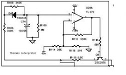
This is a comparator with positive feedback to provide some hysteresis. Although I have not studied the surrounding circuits of this speaker processor, the comparator seems to get triggered by a negative voltage, derived from a rectified audio level just before the output buffer. If the voltage across C74/C91 (left/right channel) becomes more negative than the DC level on the positive opamp input, the opamp output goes high (to the power supply) and Q5/Q6 is switched on. If this happens then the output level is attenuated a bit by R118/R159 to ground. The attenuation is not so big however, so I' m not sure what the purpose is. The positive feedback causes the DC level on the positive input to change if the opamp switches its output from low to high (or reverse). This creates a certain margin on the level after triggering before the opamp switches back. This avoids oscillation of the opamp just on the treshold of switching.
Note that Q5 and Q6 are used upside down with the collector to ground. In this way they cause a smaller DC shift on the output, a technique often used for signal muting.
Steven
Note that Q5 and Q6 are used upside down with the collector to ground. In this way they cause a smaller DC shift on the output, a technique often used for signal muting.
Steven
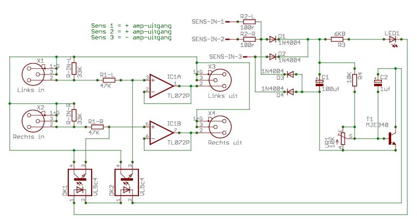
PCB Completed and being posted
Finally PCB of Subwoofer is completed, EID holidays provided me time enough to complete the PCB which otherwise is very difficult as my sales job doesn't leave enough time for hobbies, I have made the PCB for only one channel based on the fact that I'll be getting LFE out particularly for subwoofer from my dedoder, well here it is for evaluation and suggetsions for improvement are welcome before it is etched...
Rehan
Attachments
Steven said:I think the exact type is not that important. It is a feedback loop, so different LDR or LED characteristics only cause a small deviation in level where limiting starts. The speed of these devices is determined by the rate the LDR is able to change its resistance. Normally limiter attack times close to 1 ms are possible, but not much faster.
A wellknown manufacturer is EG&G Vactec (now PerkinElmer), who makes a whole series, (Vactrol). Often a VTL5C4 is used.
See: http://optoelectronics.perkinelmer.com/Catalog/Product.aspx?ProductID=VTL5C4
Also Morika makes (or has made these cells).
Steven
@ Steven,
I have a question about the VTL5C4 !
I wil use this in a speakerprotection circuit !
Like this:
An externally hosted image should be here but it was not working when we last tested it.
This is comming from:
http://sound.westhost.com/project53.htm
I hope you can/wil explane me some things, about this circuit !
Can i find you also on a audio-forum site in the Netherlands ?
This wil be easyer for me too explane my question !
I try too send you a private mail, but it wil not work !
I hope you wil help me
")
Marten77
TOINO said:
Hello Toino,
Thanks for the link !
I'm not sure of i can use the levelcontrol setup !
For my setup the Vrms wil go too about 80/90Vrms ore more !!!
This is for the sub and this can handle 700Wrms.
I use multisim 9, but i don't now exactly how too simulate it.
I'm a starter on electronics, and hope too learn how it works!
Thanks,
Marten77
- Status
- This old topic is closed. If you want to reopen this topic, contact a moderator using the "Report Post" button.
- Home
- Amplifiers
- Chip Amps
- Mystery Coponent in Subwoofer Schematics