Hi! I just got this kit in the mail today, and I've soldered it together, except for the three DC offset potentiometers.

First, what does these pots actually do? this is my first experience with LM3886's in parallel! and how do I adjust them? should I adjust them so the have the exact same value? why don't use precession resistors instead?")

First, what does these pots actually do? this is my first experience with LM3886's in parallel! and how do I adjust them? should I adjust them so the have the exact same value? why don't use precession resistors instead?
Last edited:
why don't use precision resistors instead?
A Bourns trimpot is cheaper than several 0.1% resistors.
hansibull,
Before you can adjust the pots, you will need to do some desoldering. You will first need to put a resistive load on the output of the amplifier. A 5 watt 8 or10 ohm resistor would be a good value.
For U1, disconnect one end of resistors R9 and R10. Adjust the U1 offset pot for 0 volts across the 8 ohm load resistor.
For U2, disconnect one end of resistor R7 and reconnect R9. Adjust the U2 offset pot for 0 volts across the 8 ohm load resistor.
For U3, disconnect one end of resistor R9 and reconnect R10. Adjust the U3 offset pot
for for 0 volts across the 8 ohm load resistor.
Reconnect all .2 ohm output resistors.
With this parallel configuration, if you don't remove the .2 ohm resistors as I've instructed, it will be impossible to eliminate the offset. As you adjust the offset on one of the IC's, the other two IC's will 'fight' the adjustment. It may appear that there is 0 volts offset but the IC's will be working in an attempt to balance the offset.
I'm amazed that you didn't receive these instructions with your amplifier kit.
Best of luck with your project.
Precison resistors will not help you.
Do the following:
A. Solder all 3 trim-pot meters into the board.
B. Disconnect the output resistors in one end (R7,9 and 10)
C. Put power to the board ( best if the LM3886 are cooled somehow)
D. Measure the DC-voltage between your 0V and output of the LM3886 and adjust the trim pot so it is minimum, typically a few mV.
E. Repeat D for each of the LM3886
F. Connect the 3 output resistors again.
G. Power up and play.
Not sure I like all those high value resistors needed in an inverted set-up like this, but that is another discussion.
If you really fancy precision resistors use them on your gain setting resistors in the construction
Have fun
Thomas
Yes, there should have been some instruction with this kit, but you know; it's china!
I bought this kit without the 3* LM3886, since I all ready got these from the "free samples" section form TI! I'm a bit skeptical when it comes to Ebay audio kits. This cheap kits often have lack of parts, and need to be improved with help from gurus!
Still, this kit is an exact clone of the Shine7 PA150 kit, which is said to be an excellent design.
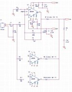
The three inputs are all connected via the 10k input resistors.
That complicates the set up.
Each channel should have it's own DC blocker, but the arrangement you have shares the DC blocker. Same for the shared Output Zobel.
All the chipamps will try to interact and may reach a reasonable average that does not cause overheating.
National's example sch using three DC servos is better.
Three properly DC blocked channels is better.
Why do Members buy kits without any customer support?
And finally, having bought cheap, expect this Forum to get them out of their self dug hole?
Last edited:
> why don't use precession resistors instead?
Because we do not know what correction is needed until we have the LM3886es in hand and powered-up.
Here's the problem. Ideally the LM3886 biases-up with its two inputs ZERO volts apart (offset voltage). In fact they can not make the two transistors exactly matched. In "precision" chips they routinely do <5mV before trimming, and sometimes <<1mV after factory trim. But the LM3886 is NOT a "precision" chip, it is a POWER chip. The processing is different. The usual designs aim for low offset, not super-low offset. We usually use DC blocking in the NFB network. If the chip is +5mV offset, we get 5mV offset at the speaker, which is plenty low.
If we do not DC-block the NFB path, offset is multiplied by gain. 5mV at the input is 100mV at the output.
But here we have three LM3886es with their outputs "shorted together". Well, take two. If one has +100mV output offset, and the other is -100mV offset, we have 200mV difference across "zero" Ohms. 200mV/0 is "infinite current" just sitting there no signal. Not Good!
So we stick 0.2 Ohm resistors in to make the "short" less short. Now we may have 200mV/0.4 Ohms or 0.5 Amps flowing uselessly from V+ at one through the resistors through the other to V-. This is 30 Watts of useless heat, and a reduction of available current to speaker.
Three chips is a little worse.
If we can trim each LM3886 to say 10mV output offset, we may have only 0.050 Amps of cross-current, which is better.
Indeed it may be folly to trim with the 0.2 Ohm resistors in circuit.
Are these "trimmers" the 50K R4 on the plan?? That appears to use input current to trim input voltage offset error. But input current and input current offset are even less well controlled than input voltage offset. And will change a lot over temperature!
I've assumed Genuine LM3886. But apparently fakes are widely available. Since they sell only on Low Price, the masks and processing won't be as precise as the Genuines, so the input errors may be worse.
There ARE better plans. Although I have never liked the original published plan. It seems like tying three ponies together to do a horse's work. They tend to not all pull the same. The differences are wasted work. This plan is quite simplified from the factory publication, which casts doubts.
Good Luck.
I've seen a much better parallel circuit than this. I think it's in the datasheet.
I would never build this circuit. It's wrong in many ways.
1) Full DC gain - bad even if they aren't in parallel. Will magnify any current sharing problems.
2) Adjustment affects AC and DC gain - in theory good, in practice bad. I wouldn't think of putting those trimpots in the AC feedback loop either.
3) Input impedance 3.3K. It's elementary to design this circuit with industry standard 47K input impedance!
It's terrible.
how can you expect a Yes/No answer to thisi was expecting a simple yes or no answer, not antagonistic reciprocity .
First, what does these pots actually do?
does the input need to be shorted? thanks
i was expecting a simple yes or no answer, not antagonistic reciprocity .
the input socket is already DC blocked.The three inputs are all connected via the 10k input resistors.
That complicates the set up.
Each channel should have it's own DC blocker, but the arrangement you have shares the DC blocker. Same for the shared Output Zobel.
All the chipamps will try to interact and may reach a reasonable average that does not cause overheating.
National's example sch using three DC servos is better.
Three properly DC blocked channels is better.
Why do Members buy kits without any customer support?
And finally, having bought cheap, expect this Forum to get them out of their self dug hole?
Shorting the input does not affect the DC conditions on the other side of the input capacitor.
The AC conditions do change when the input is shorted. That has the effect of reducing the noise generated by the input resistors.
One cannot give yes/no answer.
See my post
- Status
- This old topic is closed. If you want to reopen this topic, contact a moderator using the "Report Post" button.
- Home
- Amplifiers
- Chip Amps
- 3*LM3886 Adjust DC offset