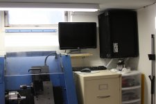
I just finished my Chip Amp and it sounds great. I was shocked at the bass that this little amp puts out and it's quite loud too! I'm running a pair of Bag End PA speakers in my workshop with 12" woofers and a compression tweeter. The speakers are big, but are very efficient and the amp is able to drive them rust fine. The amp runs cool even at full volume.
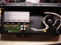
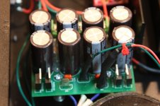
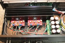
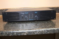
I started off this project with an amp I found at a local Pawn Shop for $40. I bought it knowing I was going to take it apart and use it for the case and I thought the price was pretty good for what it was. As a bonus it had a 18v + 18v transformer inside! It's only rated for 1.8 amps, but I figured I would give it a try and replace it if needed. I also tried a 29v + 29v transformer with a lot higher VA rating and there wasn't much of a change in volume, it just created more heat from the chip amps so I'm keeping the smaller transformer inside.
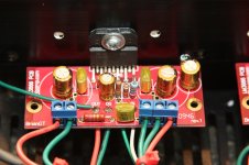
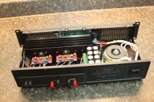
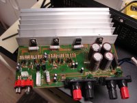
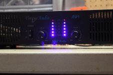
The case also had some nice LED UV meters and I had to reverse engineer the original amp circuit to figure out how to hook them up with the new chip amps. I had to pull some resistors and diodes off the old board to run inline with some of the connections for the UV meter and simply soldered them to the wire and covered them in heat shrink tubing. If you look closely at the top of the chip amp boards you can see where I had to solder a wire on to the speaker outputs to steal the signal to trigger the UV meters. It ended up working out great and everything works as it should.
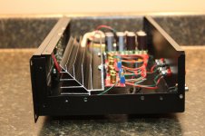
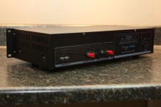
As for the case I was able to reuse a lot of the original parts, but changed out the heat sink for a larger one and also added new jacks to the back as the original ones were really cheap. The holes for the original jacks were really large so I covered them up with a piece of carbon fiber I had laying around and drilled new holes.
The first and last picture are of the original amp, and No it didn't put out 1000watts, even at 2 ohms. It didn't sound good ether so I didn't feel bad about trashing it.
Dale P.
I started off this project with an amp I found at a local Pawn Shop for $40. I bought it knowing I was going to take it apart and use it for the case and I thought the price was pretty good for what it was. As a bonus it had a 18v + 18v transformer inside! It's only rated for 1.8 amps, but I figured I would give it a try and replace it if needed. I also tried a 29v + 29v transformer with a lot higher VA rating and there wasn't much of a change in volume, it just created more heat from the chip amps so I'm keeping the smaller transformer inside.
The case also had some nice LED UV meters and I had to reverse engineer the original amp circuit to figure out how to hook them up with the new chip amps. I had to pull some resistors and diodes off the old board to run inline with some of the connections for the UV meter and simply soldered them to the wire and covered them in heat shrink tubing. If you look closely at the top of the chip amp boards you can see where I had to solder a wire on to the speaker outputs to steal the signal to trigger the UV meters. It ended up working out great and everything works as it should.
As for the case I was able to reuse a lot of the original parts, but changed out the heat sink for a larger one and also added new jacks to the back as the original ones were really cheap. The holes for the original jacks were really large so I covered them up with a piece of carbon fiber I had laying around and drilled new holes.
The first and last picture are of the original amp, and No it didn't put out 1000watts, even at 2 ohms. It didn't sound good ether so I didn't feel bad about trashing it.
Dale P.
Attachments
-
 DSC04161.JPG304.6 KB · Views: 273
 -
 IMG_6618.JPG214.2 KB · Views: 122
 -
 IMG_6610.JPG239.8 KB · Views: 136
 -
 IMG_6597.JPG242.4 KB · Views: 133
 -
 IMG_6600.JPG377.6 KB · Views: 253
 -
 IMG_6607.JPG387.8 KB · Views: 251
 -
 IMG_6631.JPG212.4 KB · Views: 260
 -
 IMG_6627.JPG278.3 KB · Views: 271
 -
 DSC04162.JPG334 KB · Views: 142
Last edited:
Yeah, after running it for hours yesterday I came to the same conclusion that the transformer needs to be a little larger. The only problem that I have is the LED UV meter uses power from the 18 volt transformer before the bridge rectifier so if I up the voltage I will have to find some way to lower it a bit for the LED's. It's a shame the UV meter didn't use DC power other wise I would just add a voltage regulator, but since it uses AC power I will have to come up with something different. I'm thinking a resistor would do the trick, but would like to know if that's the right way to go about it before trying it.
Thanks, Dale P.
Thanks, Dale P.
- Status
- This old topic is closed. If you want to reopen this topic, contact a moderator using the "Report Post" button.