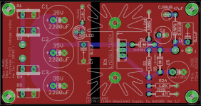
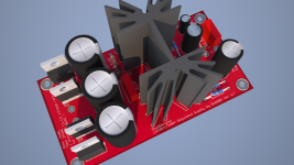
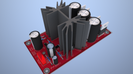
Someone told me how to remove the layers from the heatsink and now I can do a full ground plane. I also made a 3d rendering of the board so I have an idea on how it will look like. Pretty neat!
I will probably get some tantalum capacitors on the ADJ and output but for the test it's nice.
I will probably get some tantalum capacitors on the ADJ and output but for the test it's nice.
Attachments
It is advisable to drill holes on the pcb, near the periphery of the heatsink.
Gajanan Phadte
I don't understand. You mean the securing holes? I guess that at the board's size that wouldn't matter as it's pretty stiff and the weight on it is not that much but I guess I could try to fit an extra one near the heatsink somewhere.
A few comments:
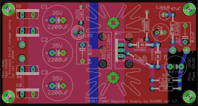
- Think in terms of power planes. There's no reason your positive power traces should be so much smaller than the ground traces.
- There's an optimal way to connect r1 and r2 for optimal performance: r1 should be connected as close as possible to the output pin of the reg, not sharing the output track (or as little as possible) and the ground side of r2/c5 should not be tied to the power groundplane but by a dedicated track directly to the gnd ouput terminal.
A few comments:
- Think in terms of power planes. There's no reason your positive power traces should be so much smaller than the ground traces.
- There's an optimal way to connect r1 and r2 for optimal performance: r1 should be connected as close as possible to the output pin of the reg, not sharing the output track (or as little as possible) and the ground side of r2/c5 should not be tied to the power groundplane but by a dedicated track directly to the gnd ouput terminal.
You mean like this?
Attachments
Last edited:
Hi Trileru,
I found from web also regulated with LT1083.
What is your main reason use LM338 ?
Hi,
Well, it's cheap and I have a dozen of so regulators already
")
That's why I mentioned that it can also be used with LT1084 etc. Just be sure to use the appropriate capacitors as per application.
- Status
- This old topic is closed. If you want to reopen this topic, contact a moderator using the "Report Post" button.
- Home
- Amplifiers
- Chip Amps
- LM338 power supply pcb, I want to make on for personal use